Project 3 - 3D printing and scanning
Part 1 - 3D scanning
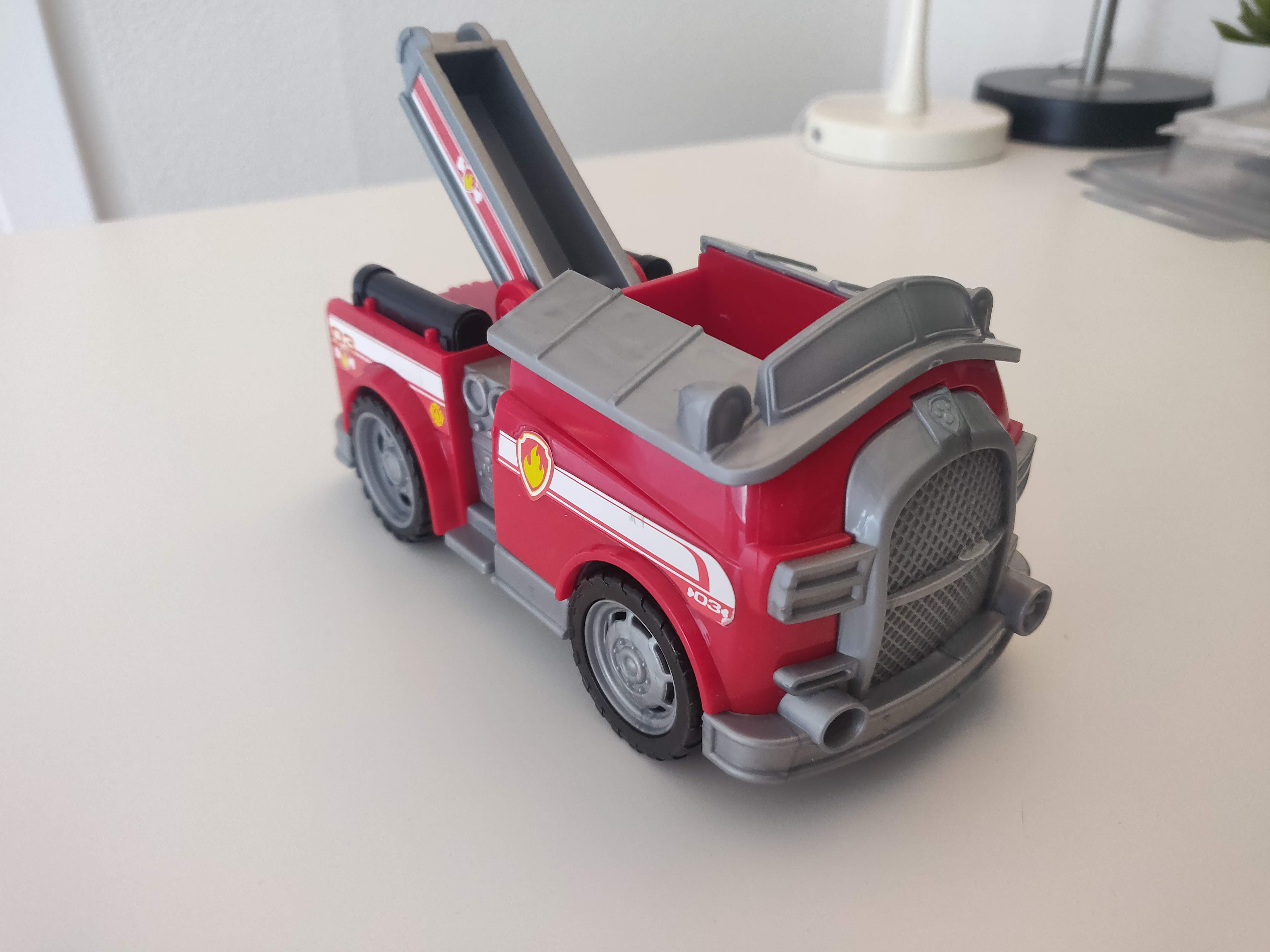
For this project I decided to scan one of my nephew's toys and I decided to start with this firetruck. I began by taking 44 photos of the truck from all angles and importing them into 3DF Zephyr free However I was unable to get it to "recontruct" more than 11 of the photos and so the resaults were no good.
Next I tried taking some 120 more pictures and since zephyr only allows 50 pictures I tried the free Regard3D . This did not work either, it alwasy gave me the error: Result file not found and after a quick google search it seemed to be a common bug with no known fix so again I set out to find a new program.
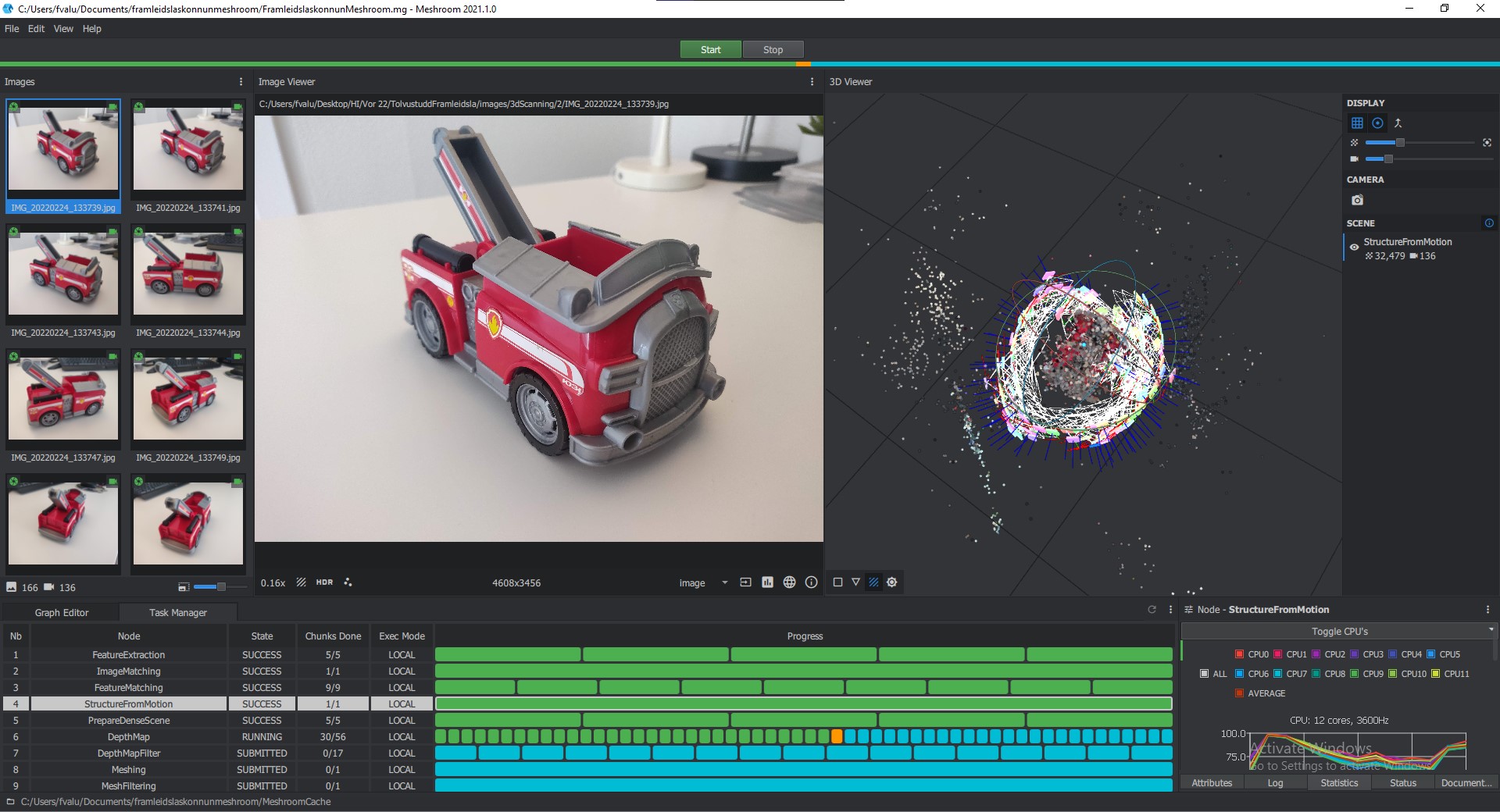
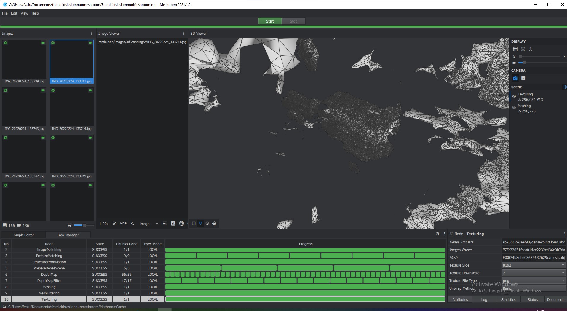
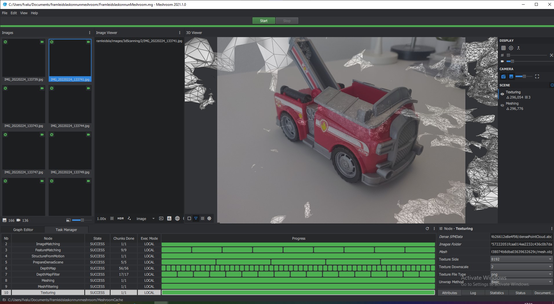
Next i tried Meshroom this one is a strange case since it was really easy to start but it gave no indication that it was doing anything. After clicking the Task manager tab it did show what it was doing. It used much of the CPU resorces available but only about 15% GPU and so was very slow despite me having a 6 core CPU and a RTX 3060 ti, the picture below is after waiting about two hours and it was only half way through.
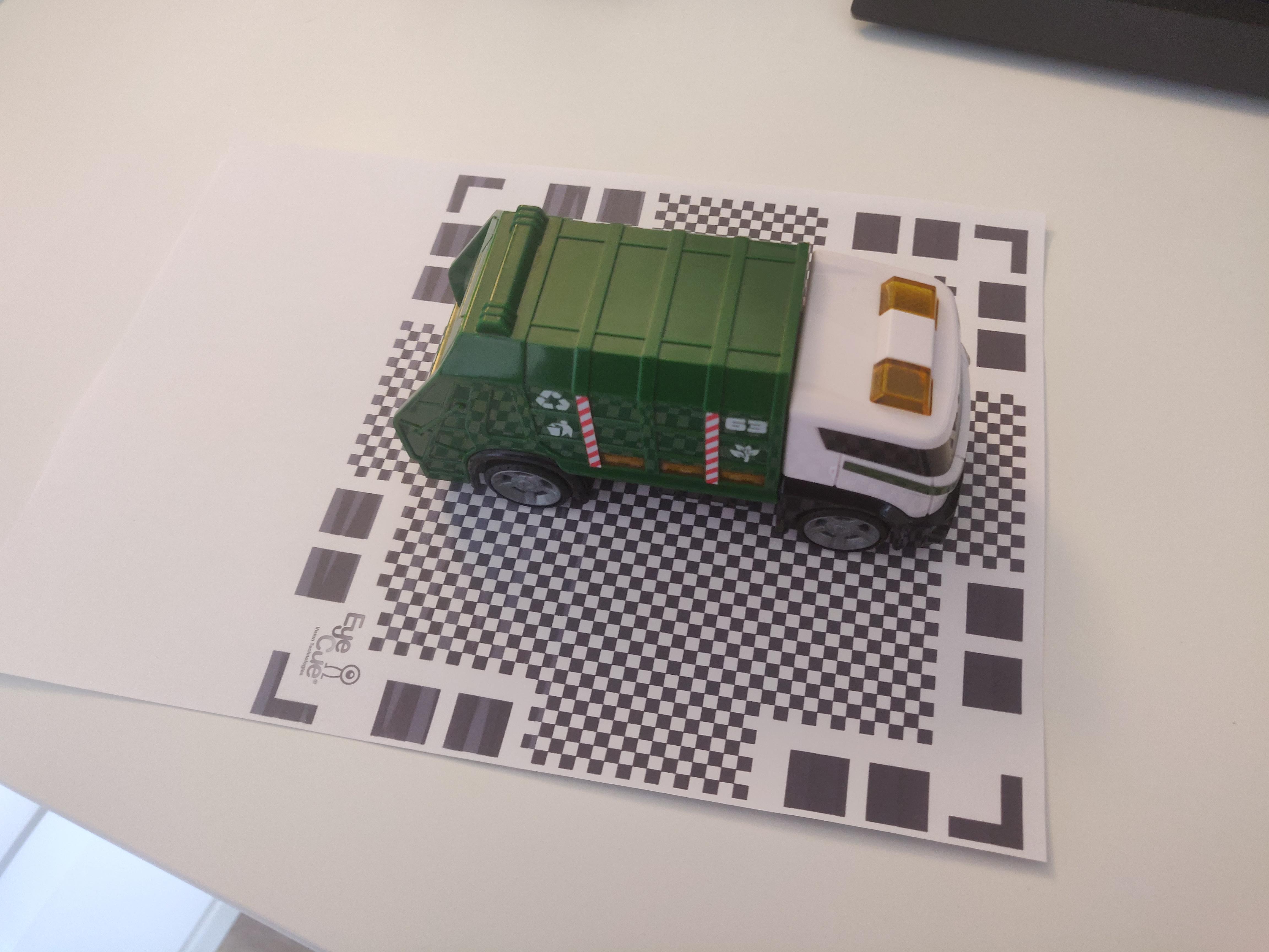
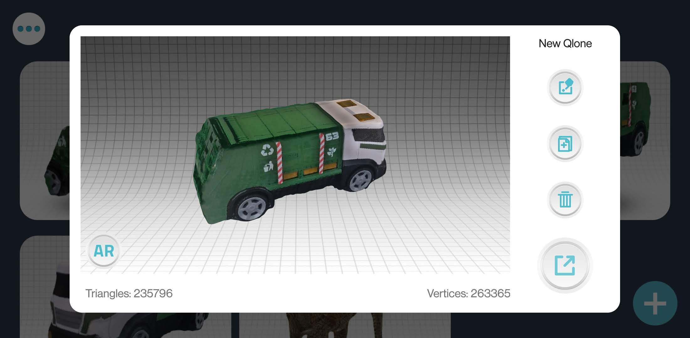
While vaiting for that I decided to google what android apps were available, Qlone was the one with the best reviews, a whole 2.1stars (an impressively low score but the other apps were even lower). For that I needed to print out this grid pattern and use a smaller object so I grabbed another toy, a dump truck this time around and followed the apps instructions.
This was much faster and easier and gave me ok resaults.
.jpg)
.jpg)
.jpg)
After a total of 3 hours of waiting meshroom it finally finished giving me something that did fit the pictures, kinda, but was nowhere close to the real thing and had no colours.

Worktime 3 hours
Wait time 3 hours
Total 4 hours
Part 2 - 3D printing
Gathering ideas
Again me and Sæmundur desided to work together on projects 2 and 3 since in another class we are creating a soup feeding robot and thought that combining that project with laser cutting and 3D printing would be perfect. We chose to use Autodesk Fusion 360 as our CAD tool since it was recommended by the teacher, has relatively simple control over kerf (will be explained later) and has built in support for easy collaborations between users.
For the 3D printing I got the task of making the elbow joint and the wrist joint, he made the shoulder joint and a fan housing. Here was one of my main inspirations for this project though the two projects are excecuted in very different ways.
Worktime 1 hours
Testing the printer
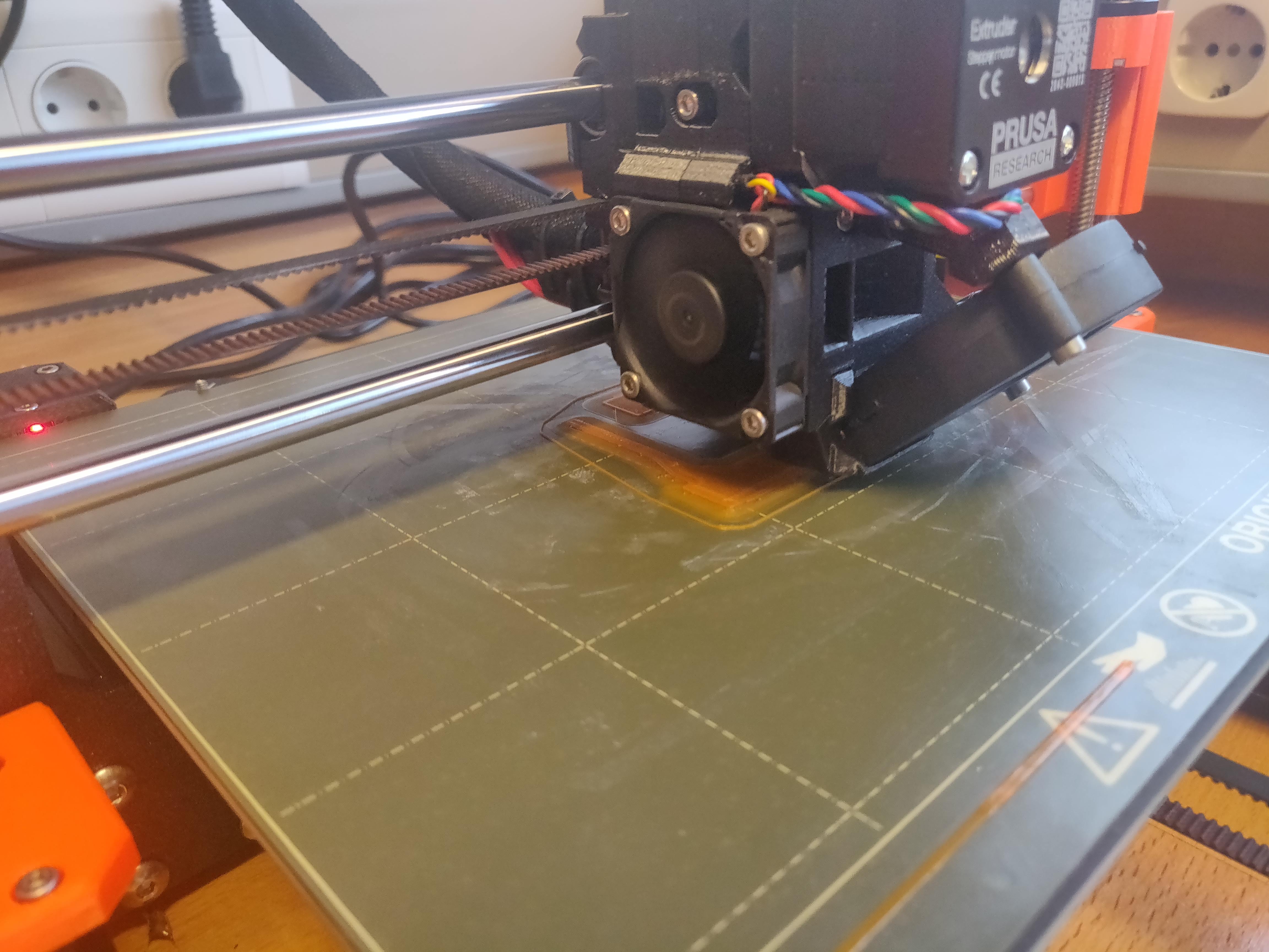
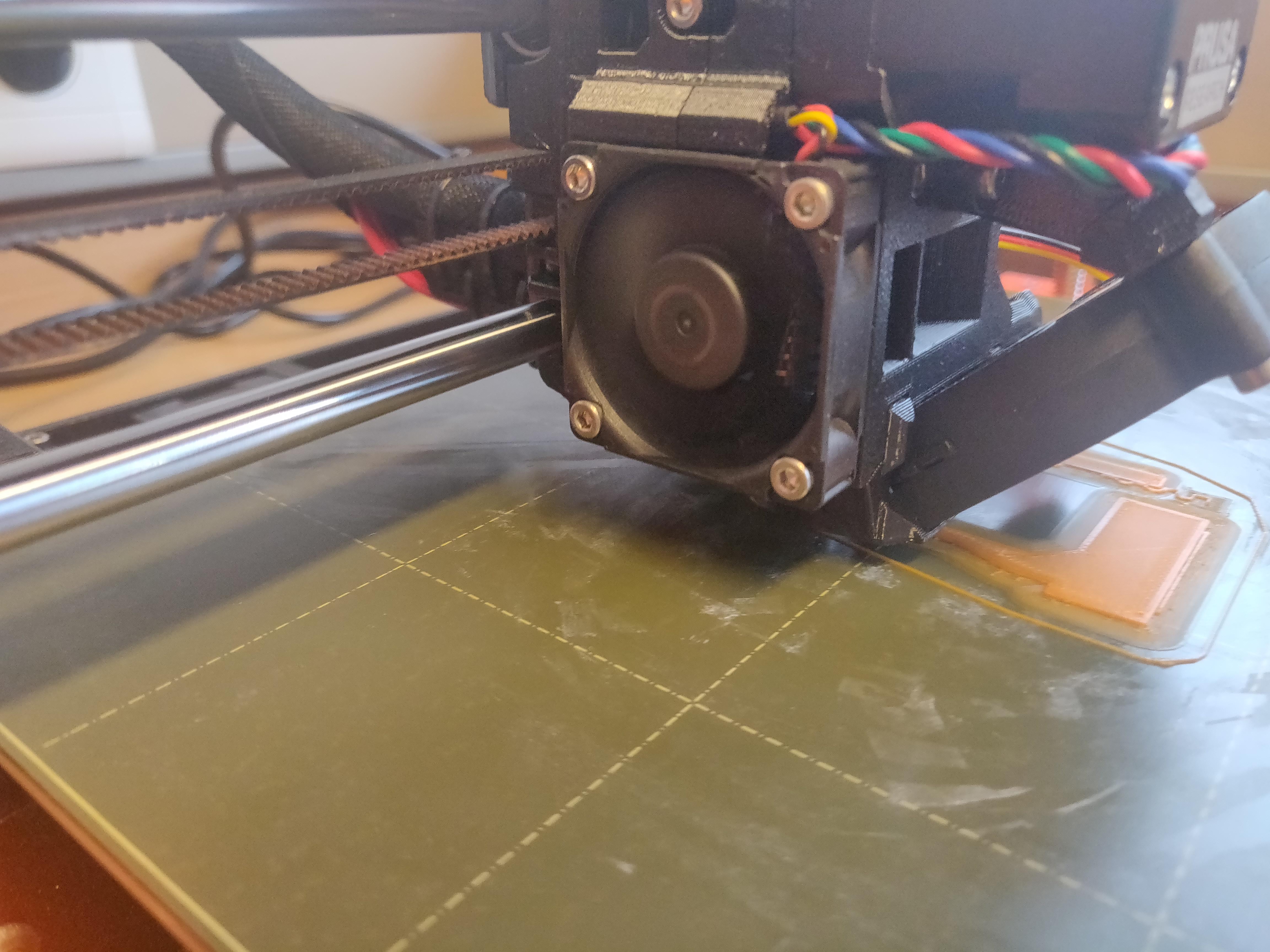
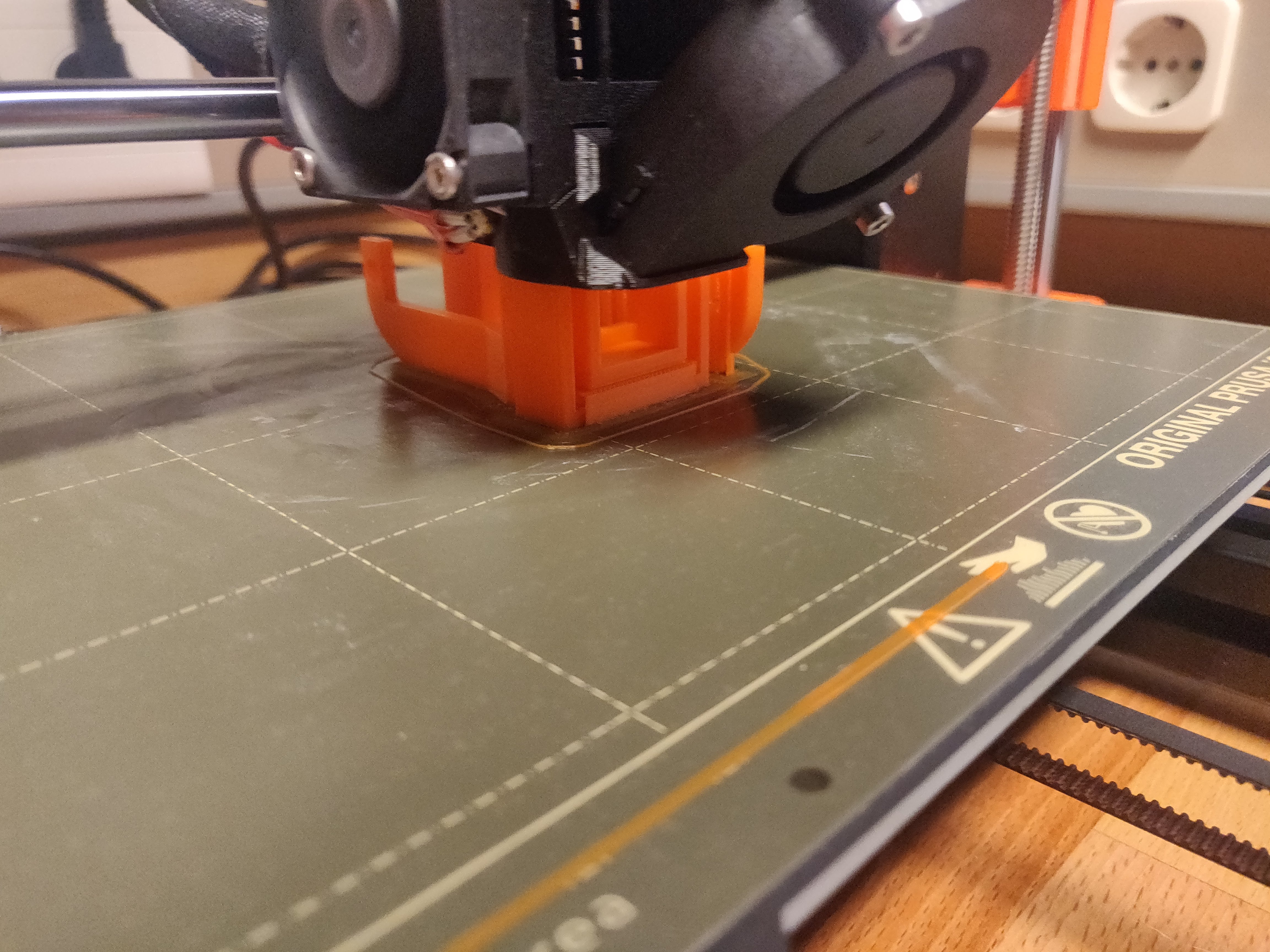
We used 2 Original Prusa i3 MK3S+ 3D printers for our work, one of them with the MMU addon for multiple filaments. To test them we used mini all in one 3D printer test to test the printers on PLA, and we used all standard settings in PrusaSlicer , 0.15 mm layerheight and 15% infill. It could handle overhangs of up to 80 degrees but with some problems after 70 degrees, perfectly handled bridging upto 25 mm and well enough up to 40 mm. Height, length and width tests were perfect but circles had a tiny bit smaller diameter than they were supposed to and there was a bit of stringing but nothing bad. For our purposes the printer worked perfectly but you can see that it puked a bit at the end which could have failed the print if it happened at the wrong place at the wrong time.
.jpg)
.jpg)
.jpg)
.jpg)
.jpg)
.jpg)
.jpg)
.jpg)
.jpg)
Worktime 2 hours
Printtime 3 hours
The elbow joint
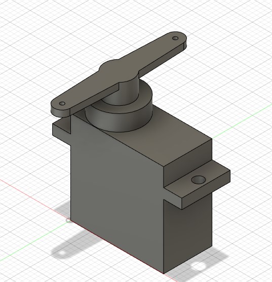
This joint needed to be made to fit my towerpro SG-5010 servo, I found some of the dimensions online but not the ones that matter and so I began by measuring and drawing it up in Fusion.
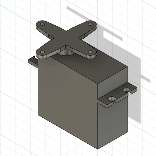
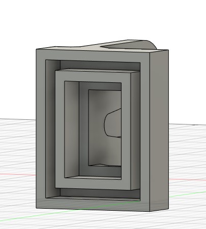
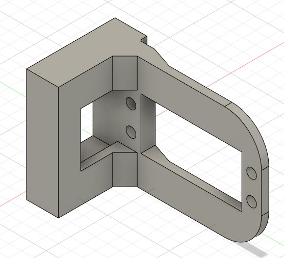
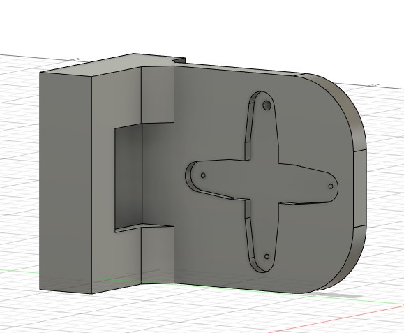
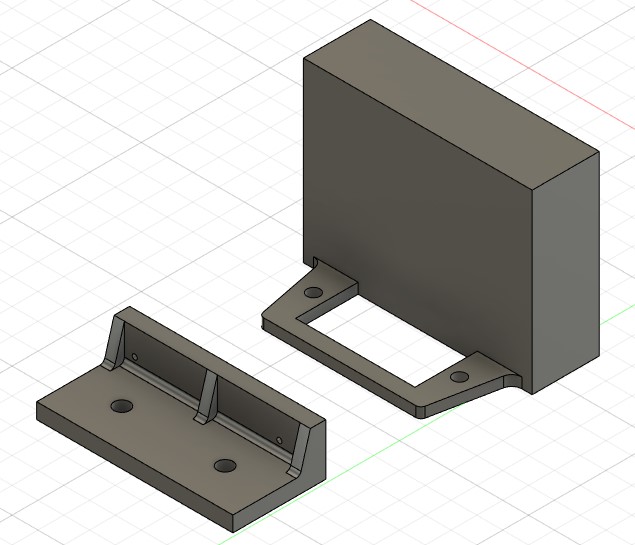
Then I began by making the part of the joints that fits over the ends of the arms since it is shared with all 4 inserts on the robot, I gave it the thickness of 3 mm and made it go 10mm up the arm. This is visible on the left most image below. Then I went on to design the insert in image 2. These two were designed to keep the two arms in line and to provide >180° of movement.
All 4 of the 3D printed parts I drew were made with heavy use of scetching, extruding that and then repeting on the newly created face.
After designing this joint it was time to print it, we have access to a prusa printer so I began by exporting a 3mf file from fusion and importing that into PrusaSlicer Setting infill to 50% since these parts need to be strong and painting on supports under the overhangs. I forgot the supports at first but thankfully i realised that only 10 minutes in to the print so it was allright. I used orange prusa PLA for all of my prints,
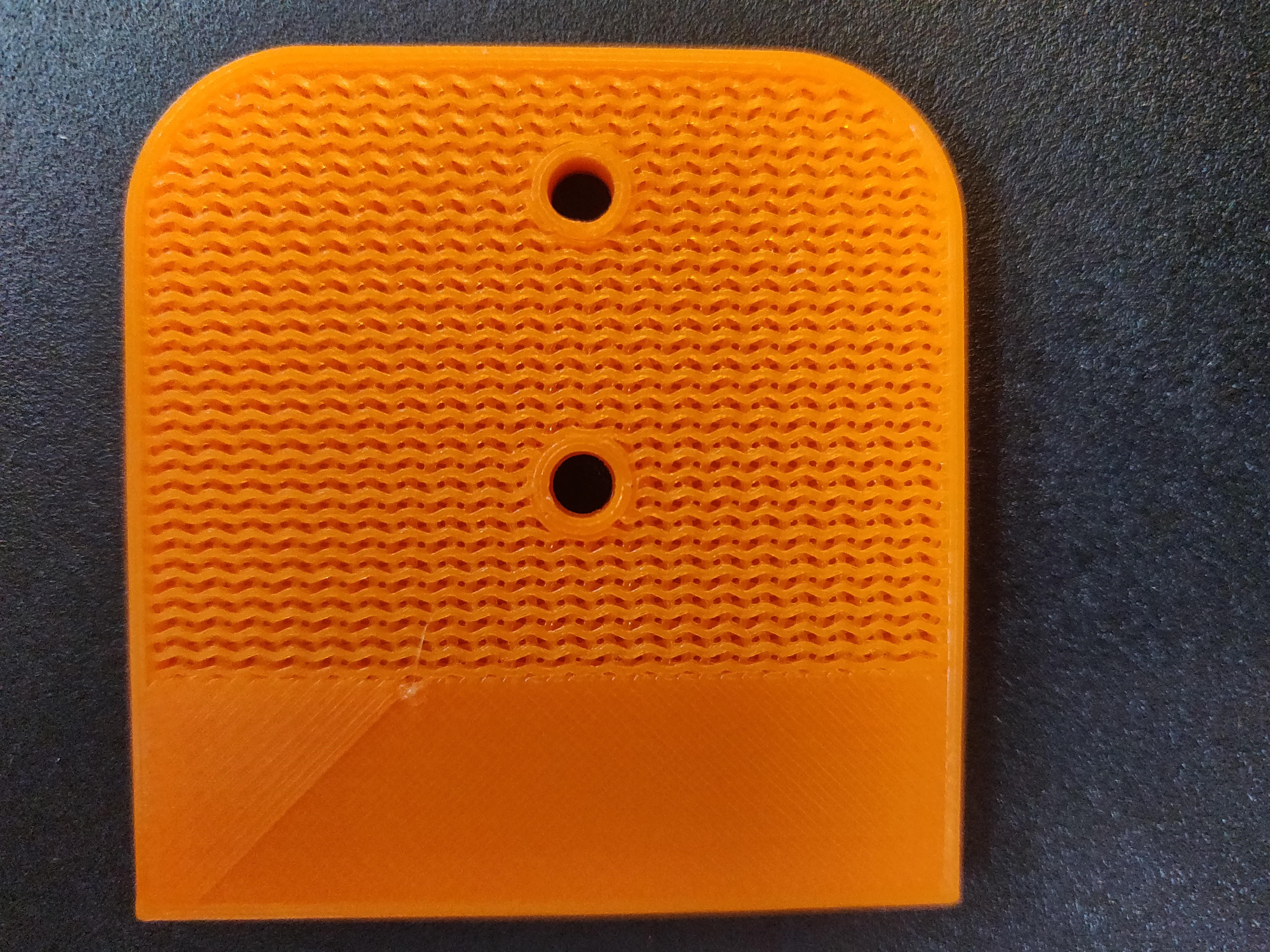
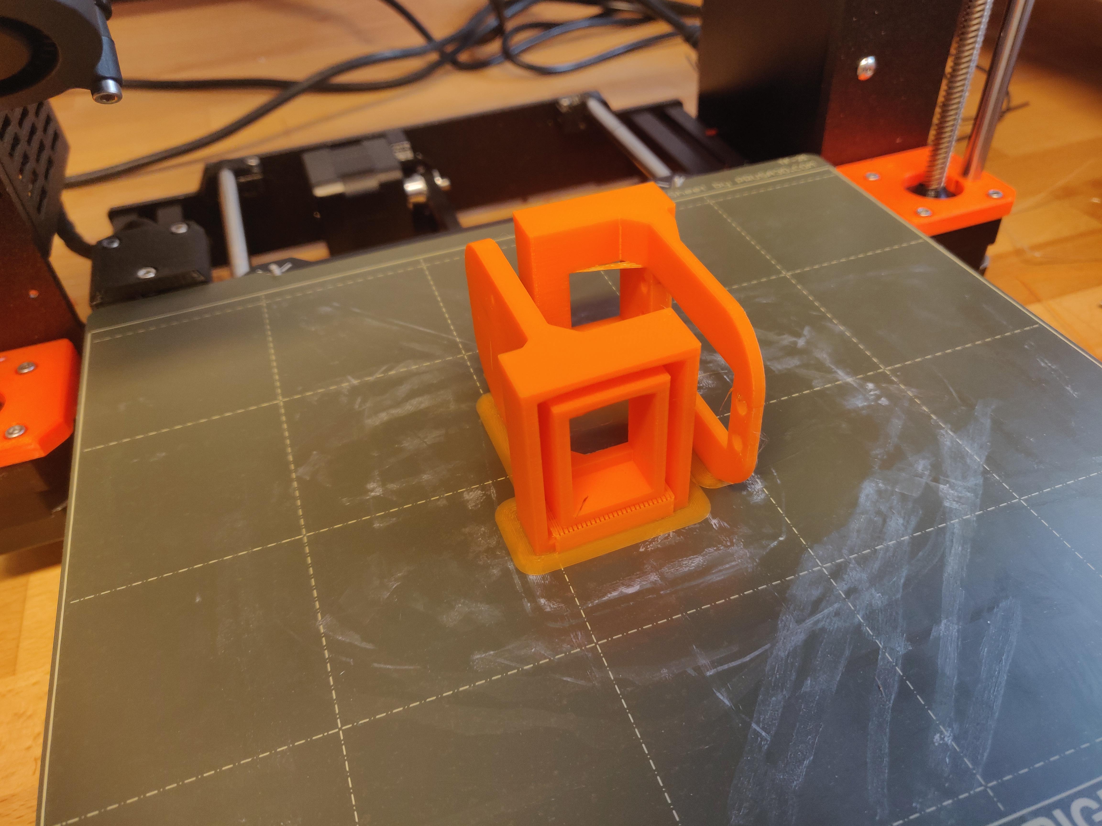
Sæmi had started his print an hour earlier than me and also forgot supports but that gave us this pretty reject.
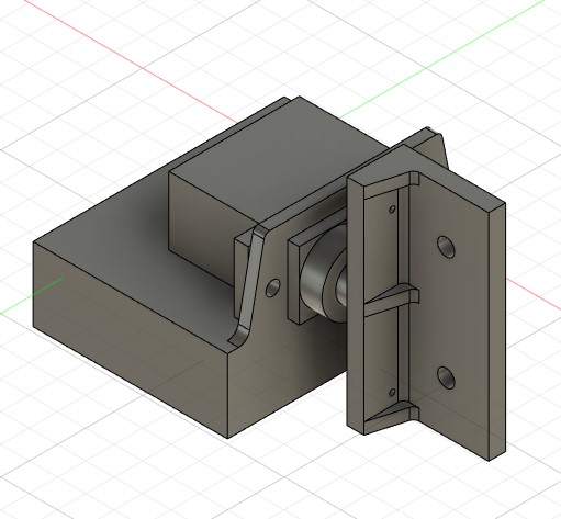
So we added the supports and started the print again, this time it worked perfectly and so six hours later we had these 2 pretty pieces
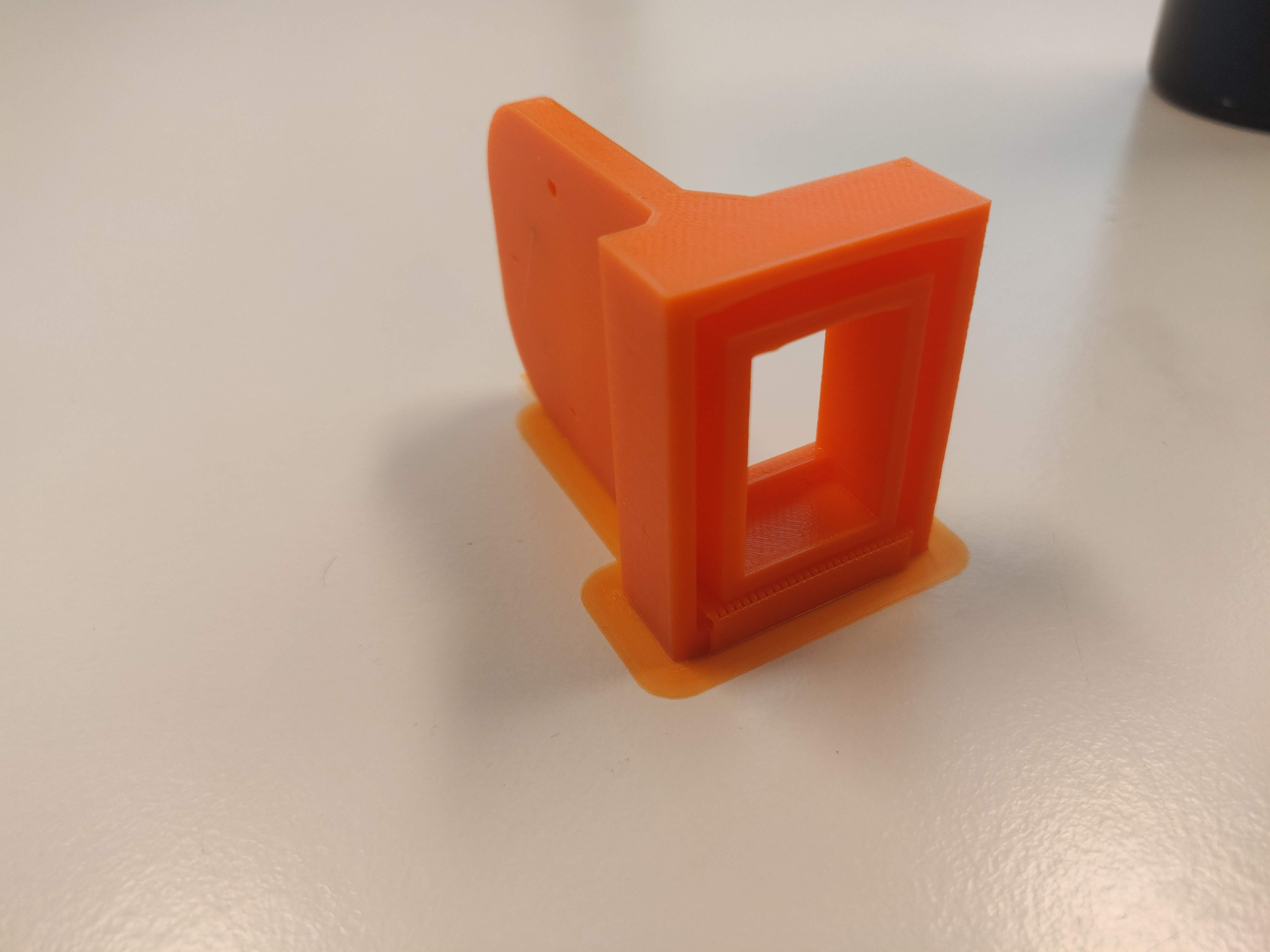
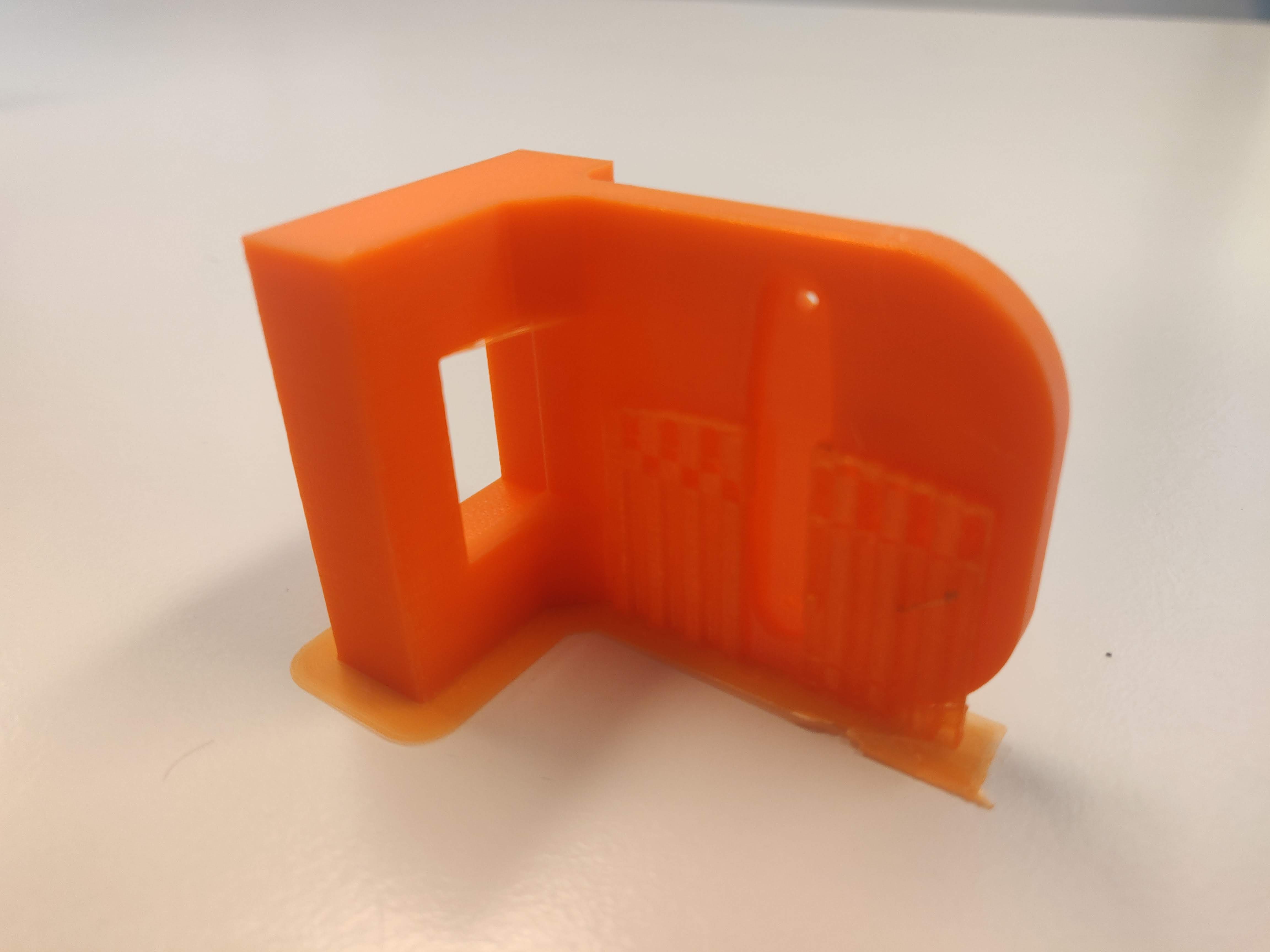
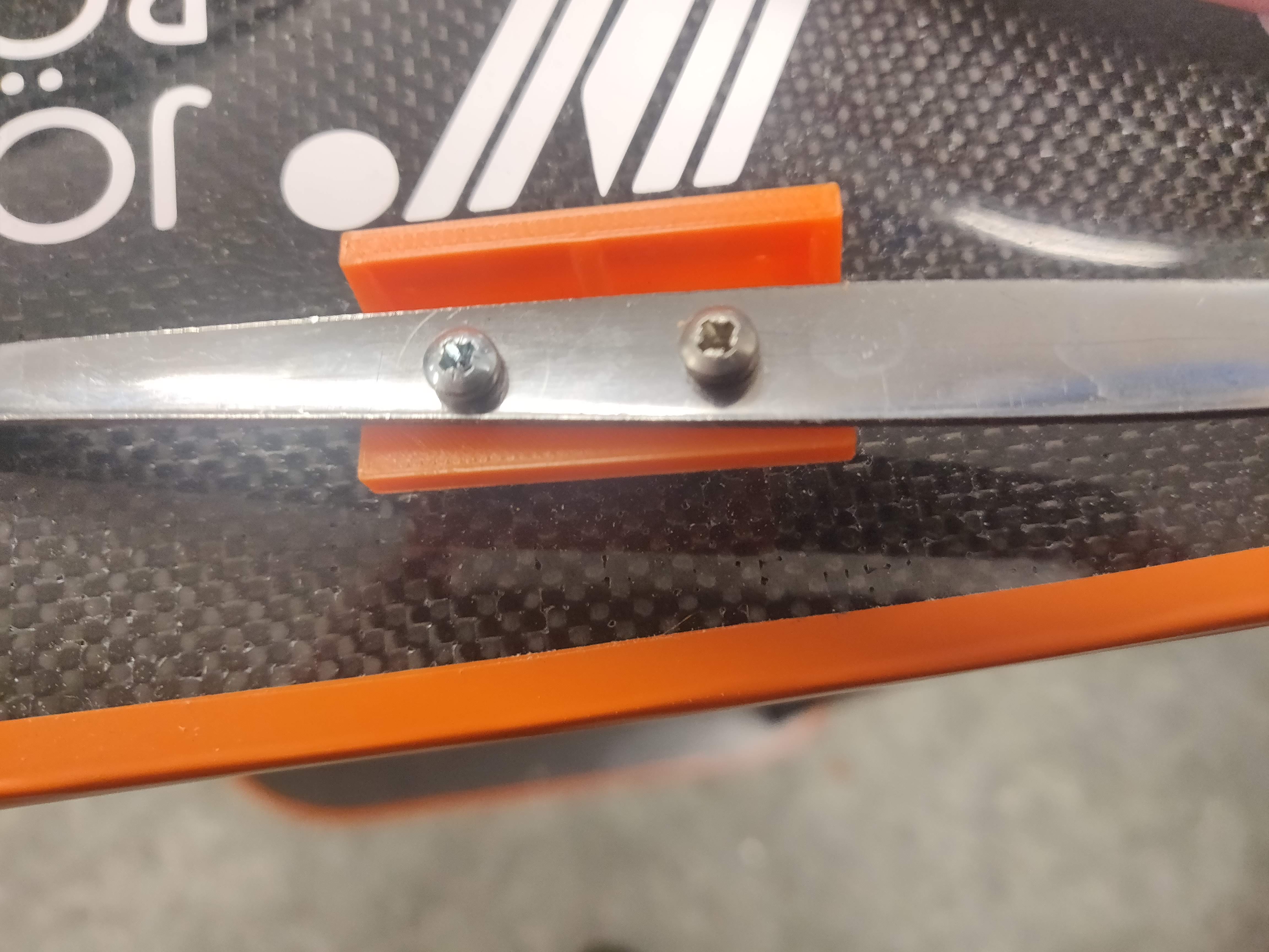
After printing I realised that although the Elbow did indeed have about 200° of movement they were in the wrong place And I actually needed to offset the lower elbow joint 90°, the one with the big hole in the middle seen in the second to last photo above. This reqiered some "adjusments" to the insert but eventually it fit though it was now fastened with bolts through two new holes in it and the arm. But the upper elbow joint press fit perfectly... after alot of sanding down of the arm since the acrylic was 3.15 mm thick but not 3 mm like I thought it was.
Worktime 8 hours
The wrist joint
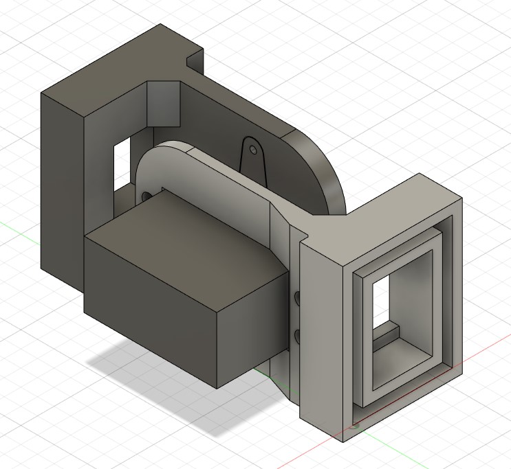
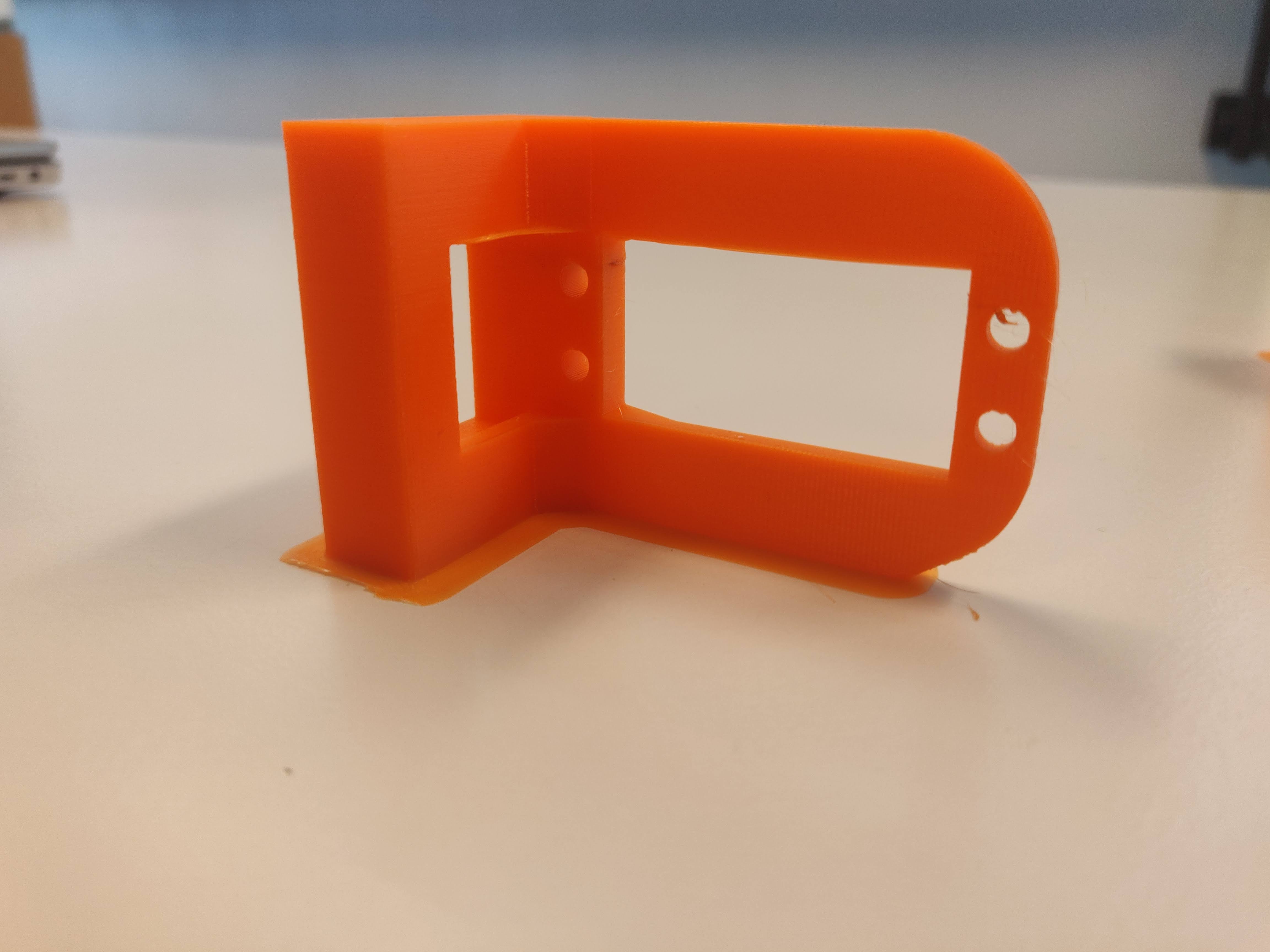
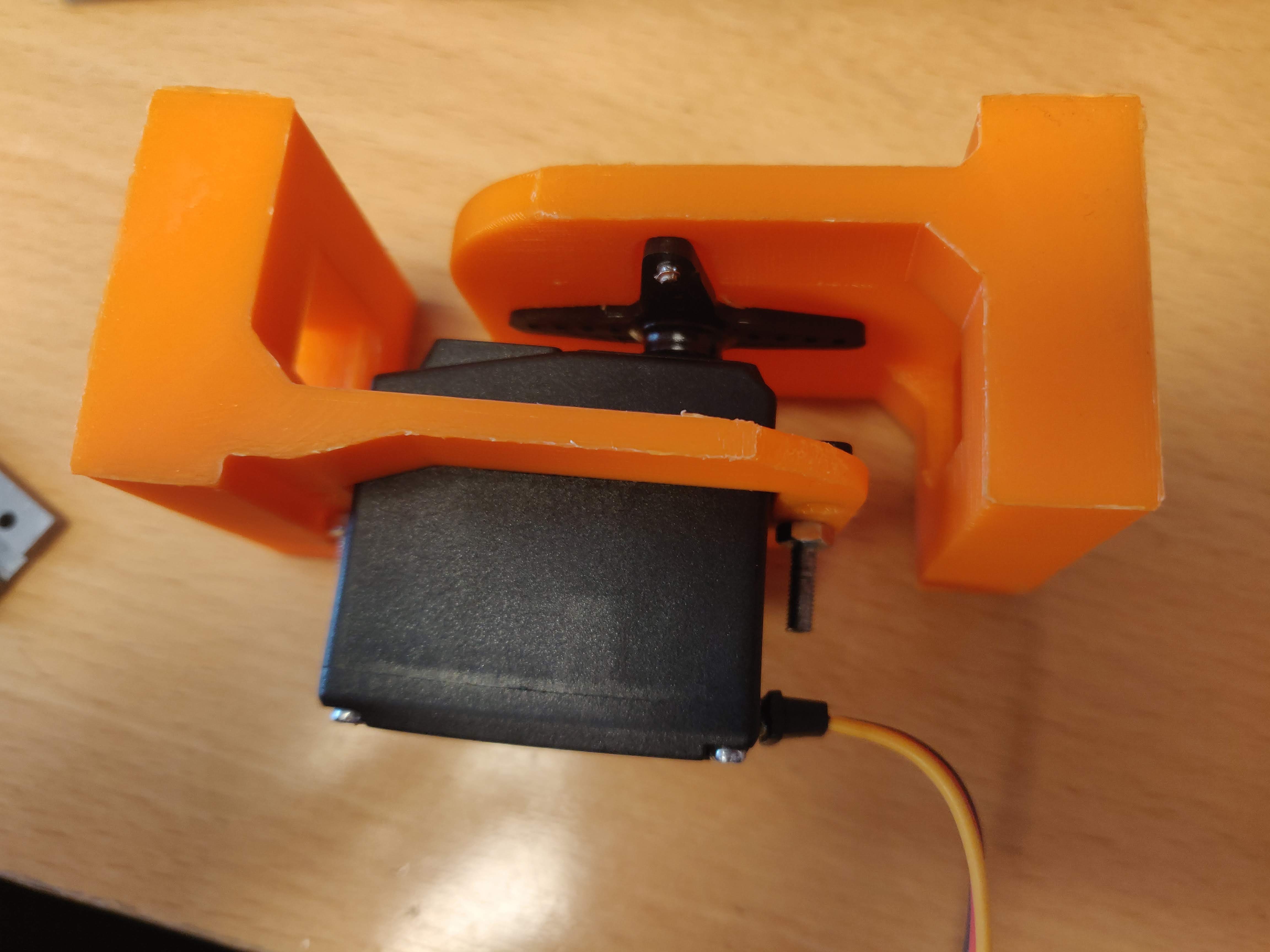
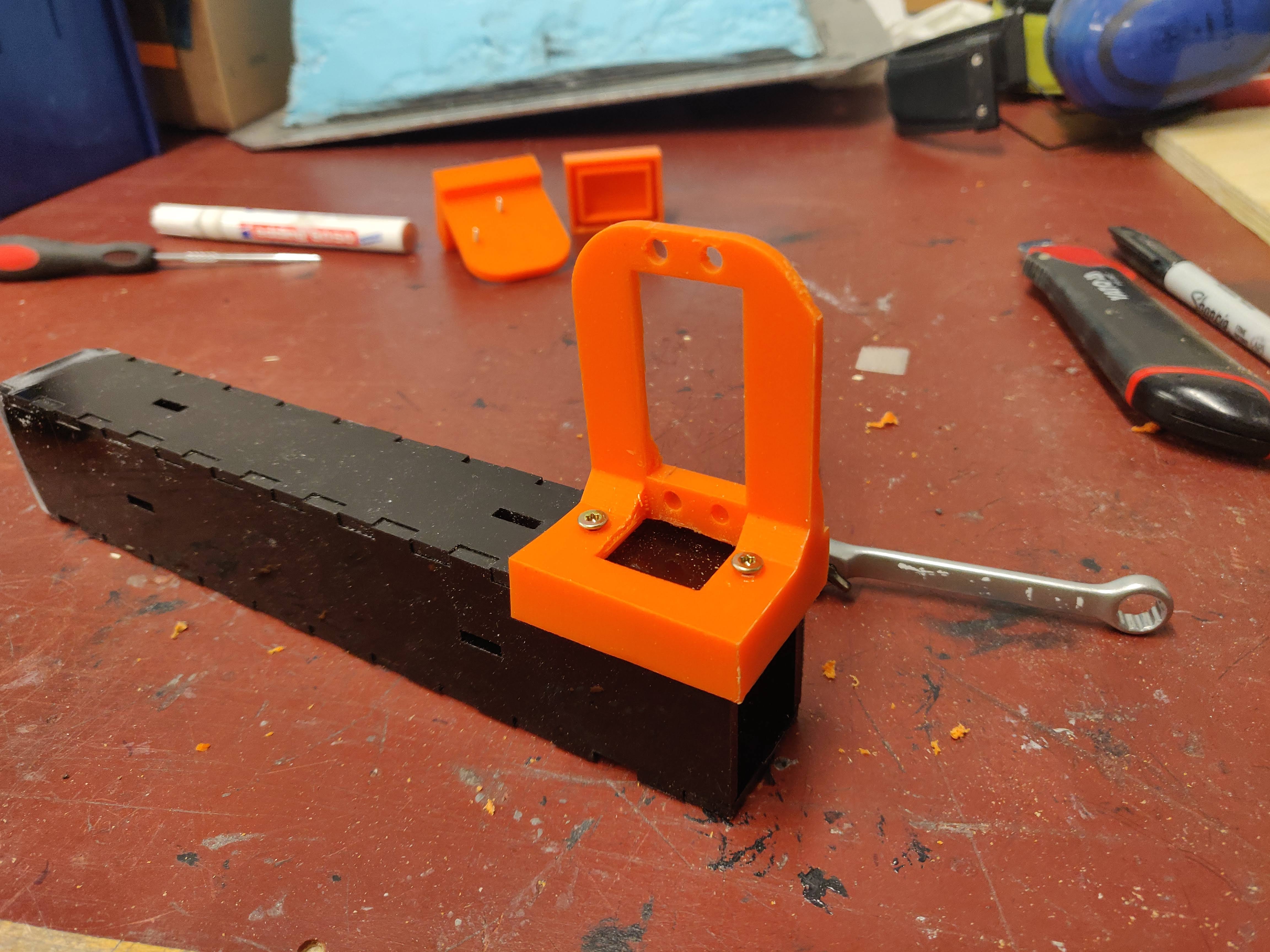
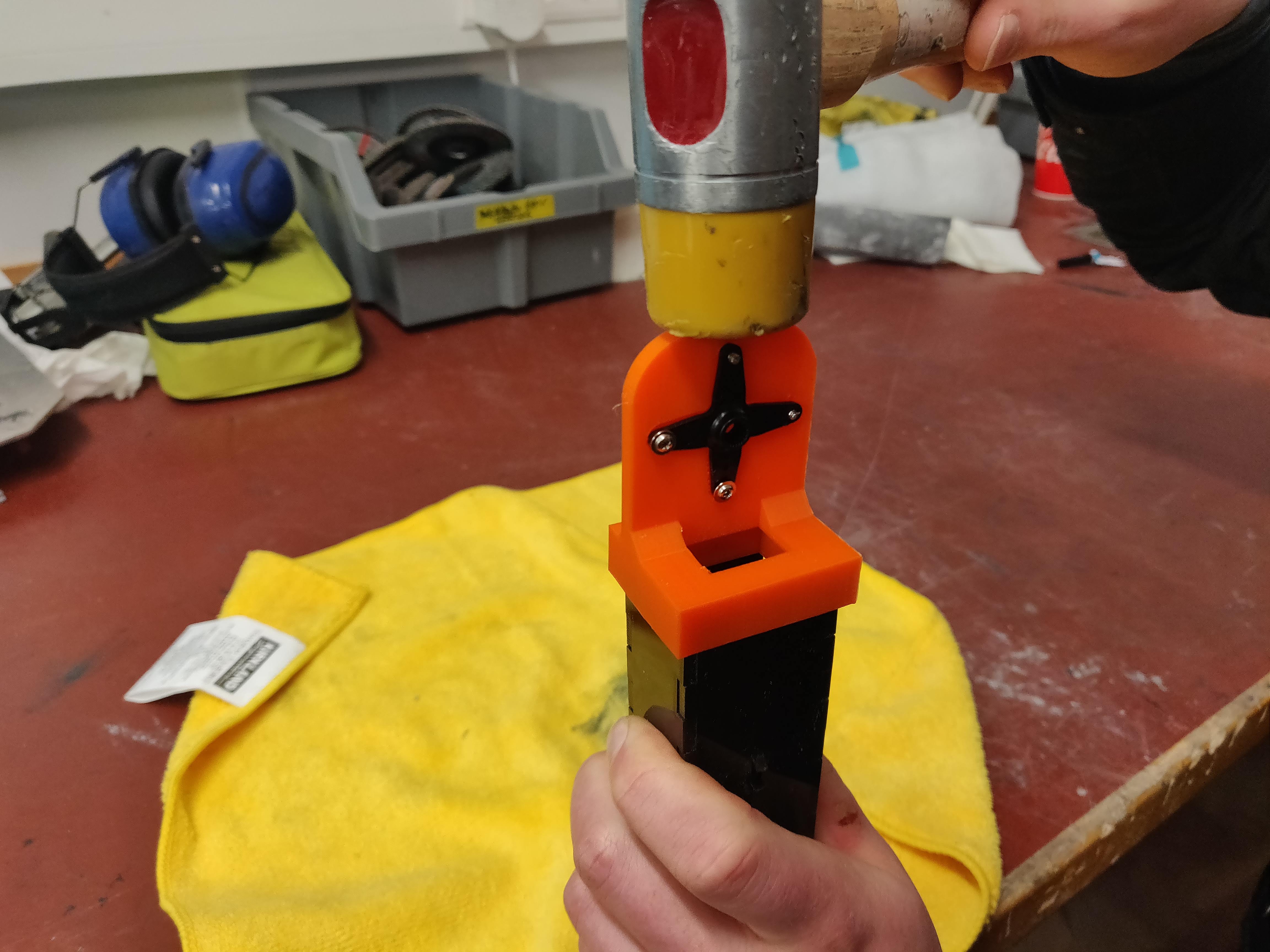
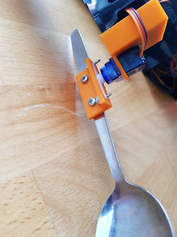
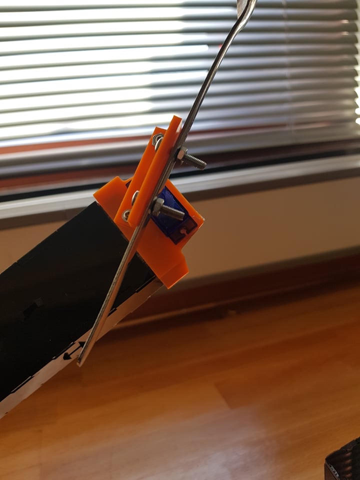
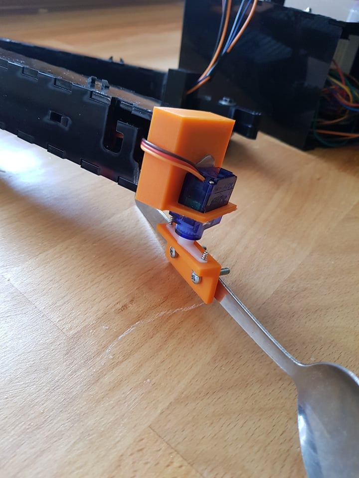
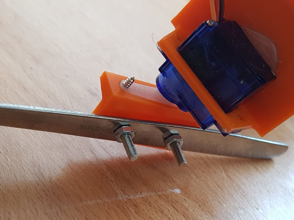
The wrist joint fastens together a spoon and the upper arm with a small sg90 servo in the middle. Again I began by measuring and drawing the servo in fusion before building the joint around it.
This joint was alot simpler to design
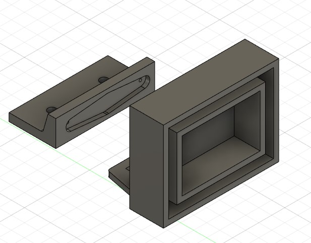
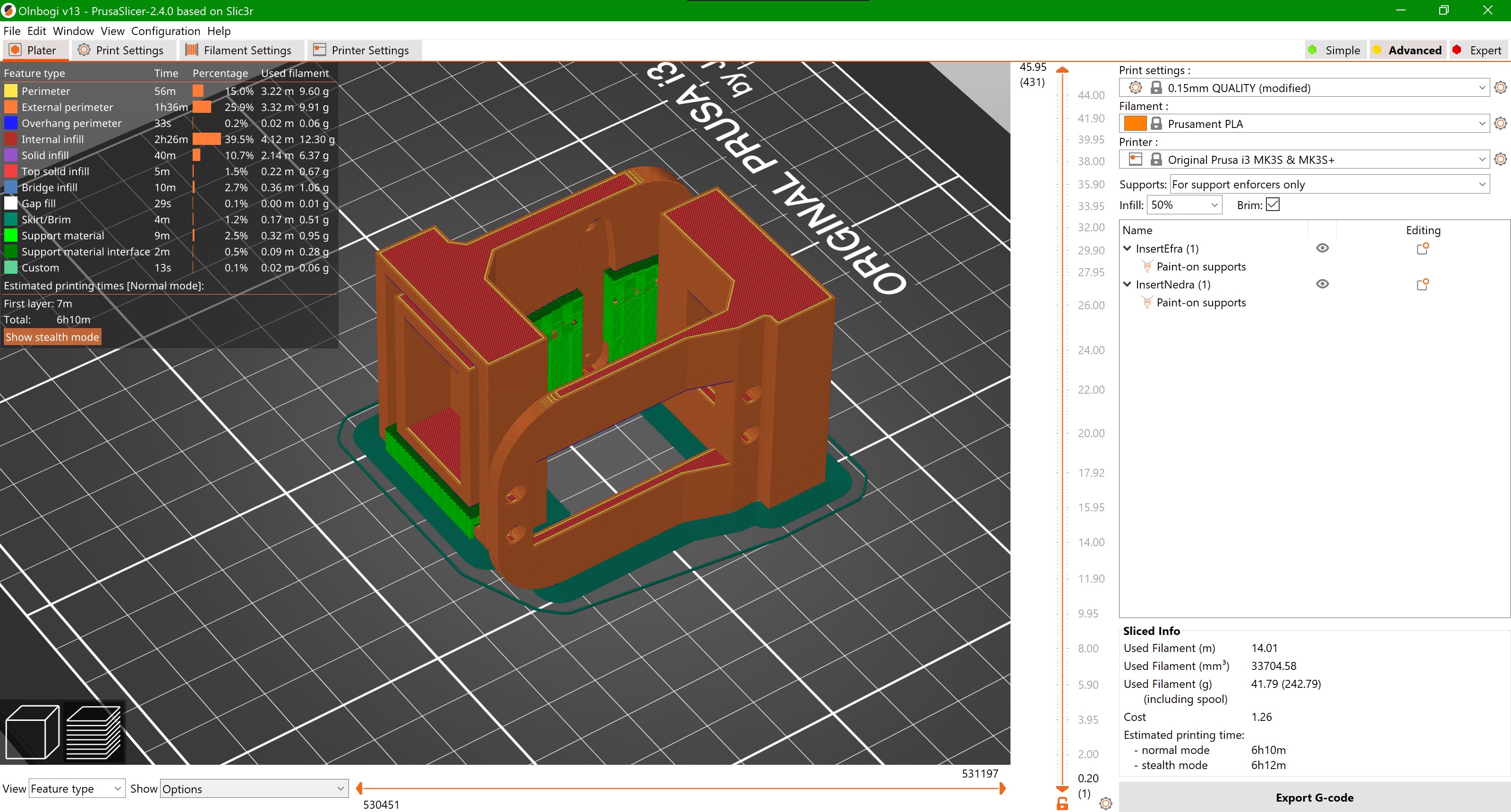
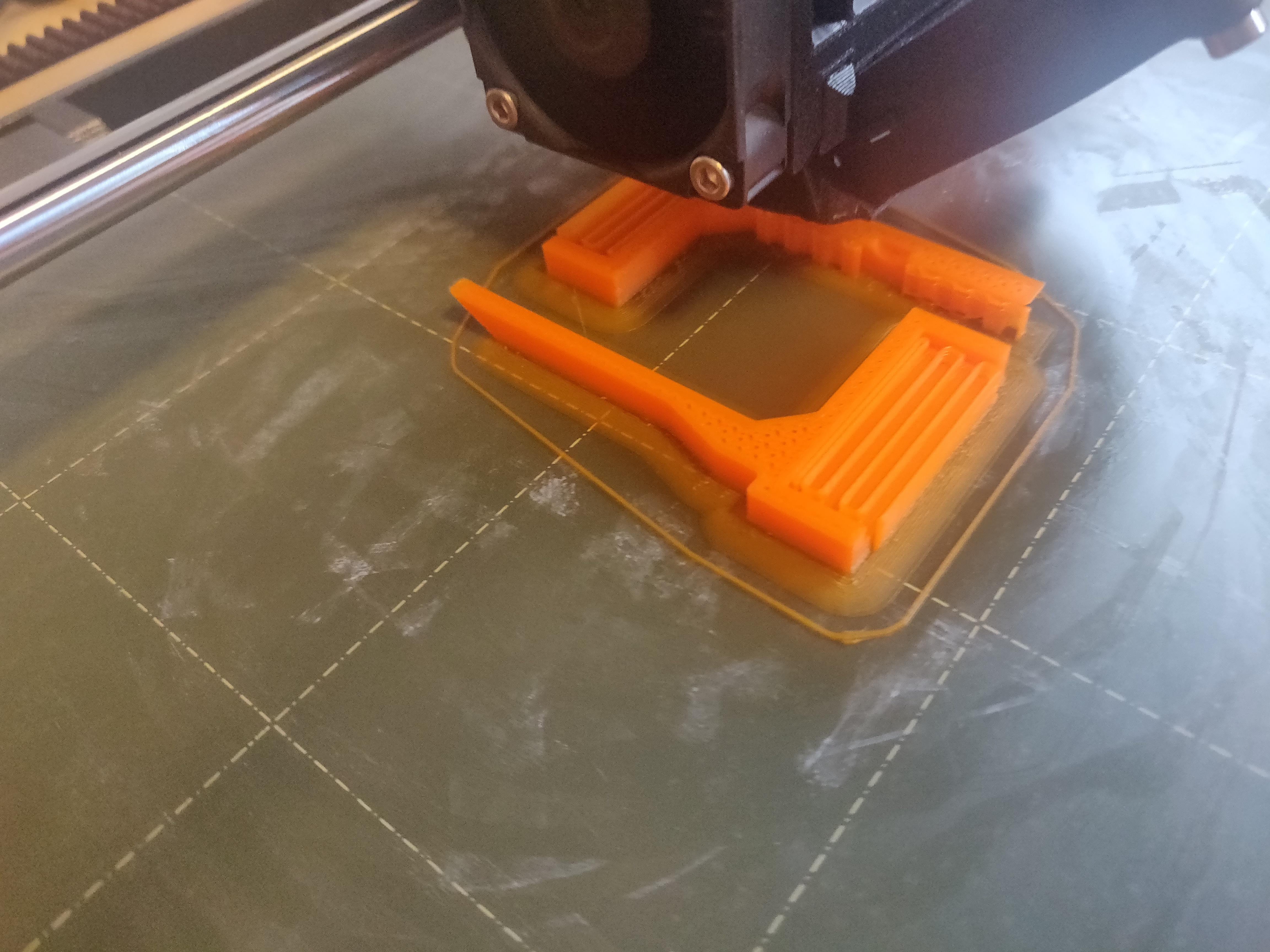
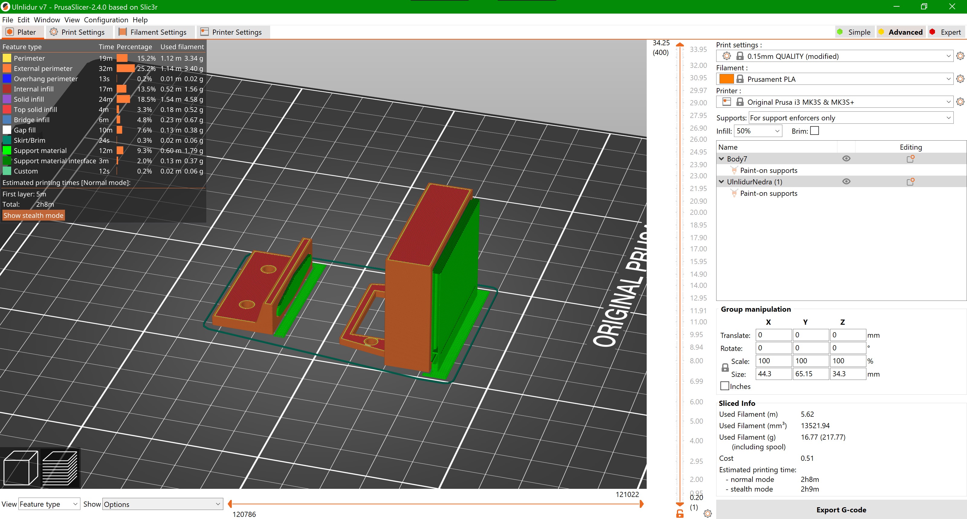
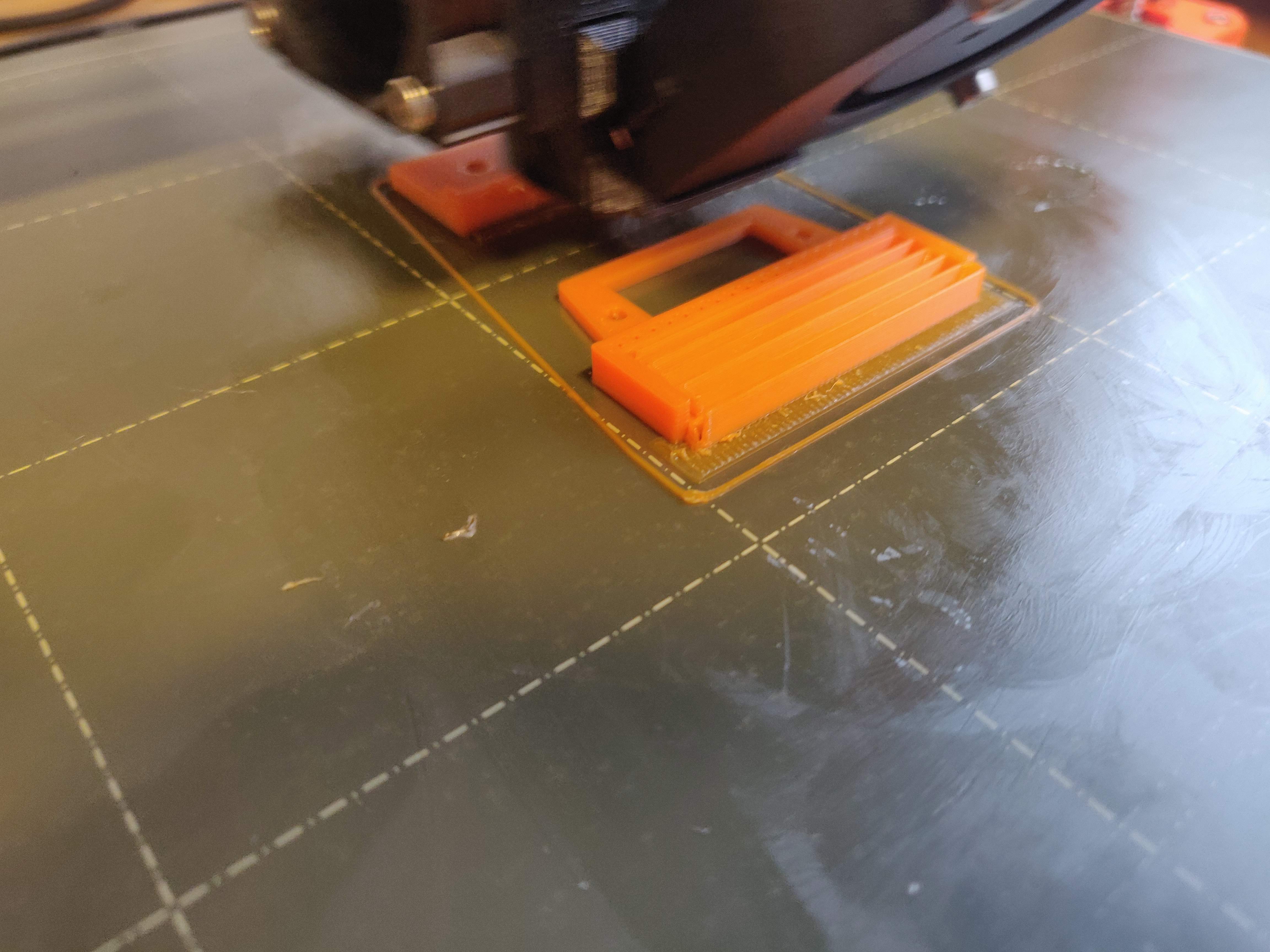
Here jou can see how I sliced it, again with 50% infill and painted on supports for overhangs.
This one came out perfect on first try as you can see
Worktime 3 hours
Finally here you can see a video of us testing both the elbow and wrist of the robot
Here are the files for the elbow and wrist
Total worktime 14 hours
Total printtime 16 hours
Work on website 6 hours