Project 2 - Computer aided cutting
Part 1 - Vinyl cutter
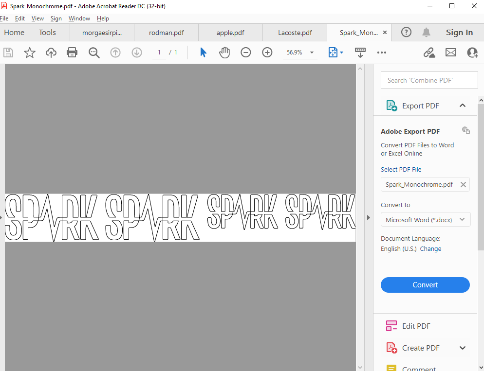
For the vynil cutting part of this project I decided to cut out the logo of Team Spark, the Formula Student team that I am a part of. I started with a full colour version of the logo made in adobe illustrator and imported that into inkscape.


There i set fill to none, stroke paint to flat colour/black and stroke style width to 0.02mm. Now the logo was ready but I copy pasted until I had four of them in two different sizes. Then I exported as a pdf, selected the putter as a printer, clicked properties and clicked get from machine to see the length of the image, and put in a langth about 2 mm larger.
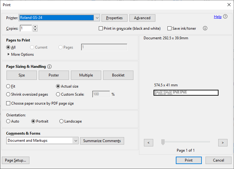
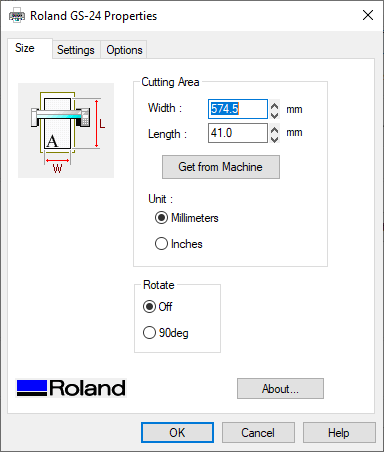
After that I put in the vinyl that I wanted to use, told the cutter to find the edge and pressed print.
Here you can see the cutter in action
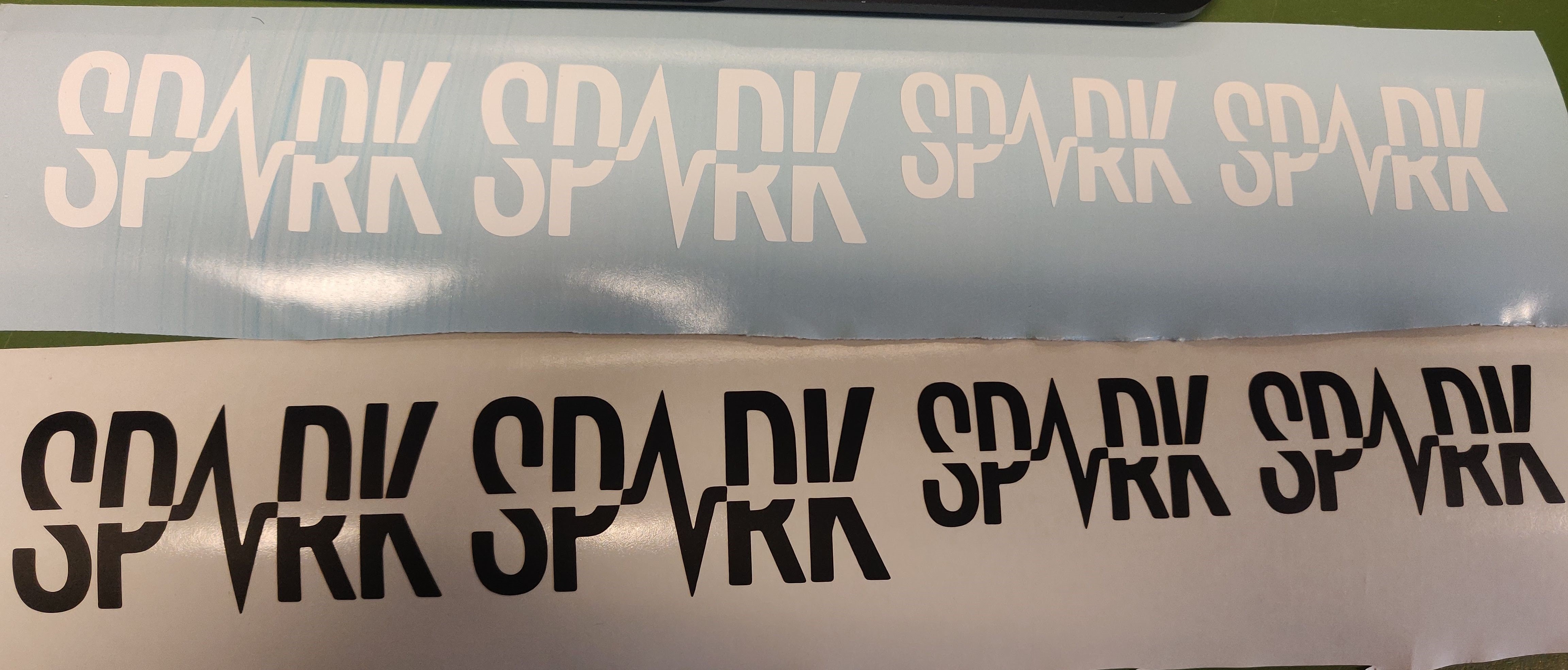
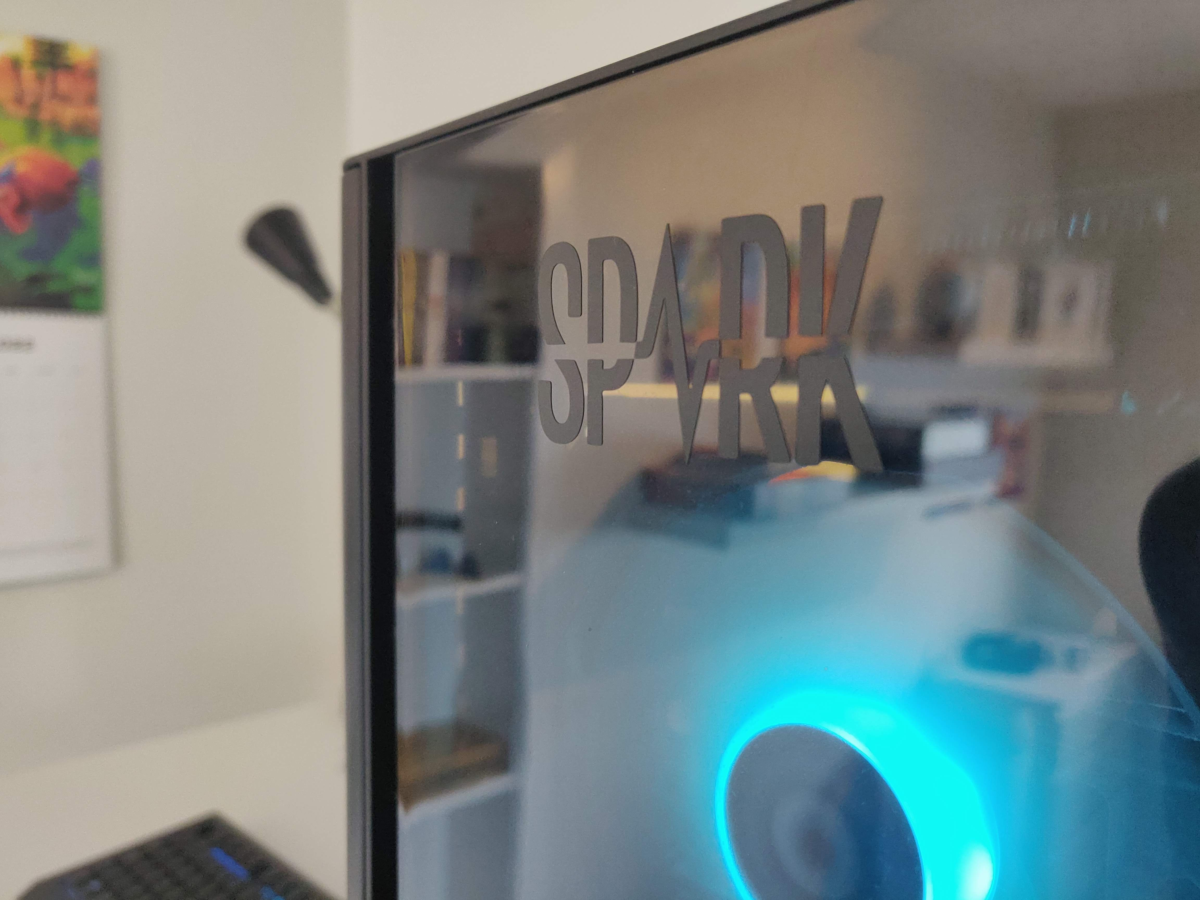
And here you can see the finished pieces, still on the canvas and on my pc.
Worktime 1 hour
Work on website 1 hour
Part 2 - Laser cutter
Gathering ideas
Me and Sæmundur desided to work together on projects 2 and 3 since in another class we are creating a soup feeding robot and thought that combining that project with laser cutting and 3D printing would be perfect. We chose to use Autodesk Fusion 360 as our CAD tool since it was recommended by the teacher, has relatively simple control over kerf (will be explained later) and has built in support for easy collaborations between users.
I got the task of creating the arms of the robot that will provide strength and keep all the wires in the right places. Here was one of my main inspirations for this project though the two projects are excecuted in very different ways.
Worktime 2 hours
Measuring kerf
Kerf is a measurement for the amount of material removed by the laser, to ensure a tight fit you must extend all edges half of that amount which can prove a bit tricky but thankfully fusion has built in tools to take care of it.
Here you can see Sæmundurs documentation of the whole process of measuring the kerf for the laser cutter at the HÍ FabLab but I will include the results. The following settings were used giving a kerf of 0.133 mm for the acrylic and 0.167 mm for the plywood.
| Material | Parameter | Value |
|---|---|---|
| Plywood | Preset | Wood cutting 6 mm |
| Plywood | Speed | 20% |
| Plywood | Thickness | 4 mm |
| Acrylic plastic | Preset | Acryl 3 mm |
| Acrylic plastic | Speed | 30% |
| Acrylic plastic | Thickness | 3 mm |
| Both | Autofocus | Thickness |
| Both | Air outlet | ON |
Worktime 1 hour
Creating test fits
The arms will be made out of rectangular tubes, taller than they are wide to increase strength, with built in cross bracing and wiring holes at the end of the top piece. Sounds a bit complicated but will be very simple when you look at the finished product.
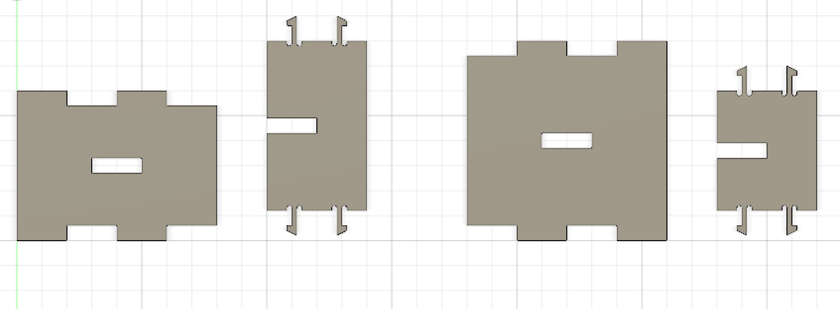
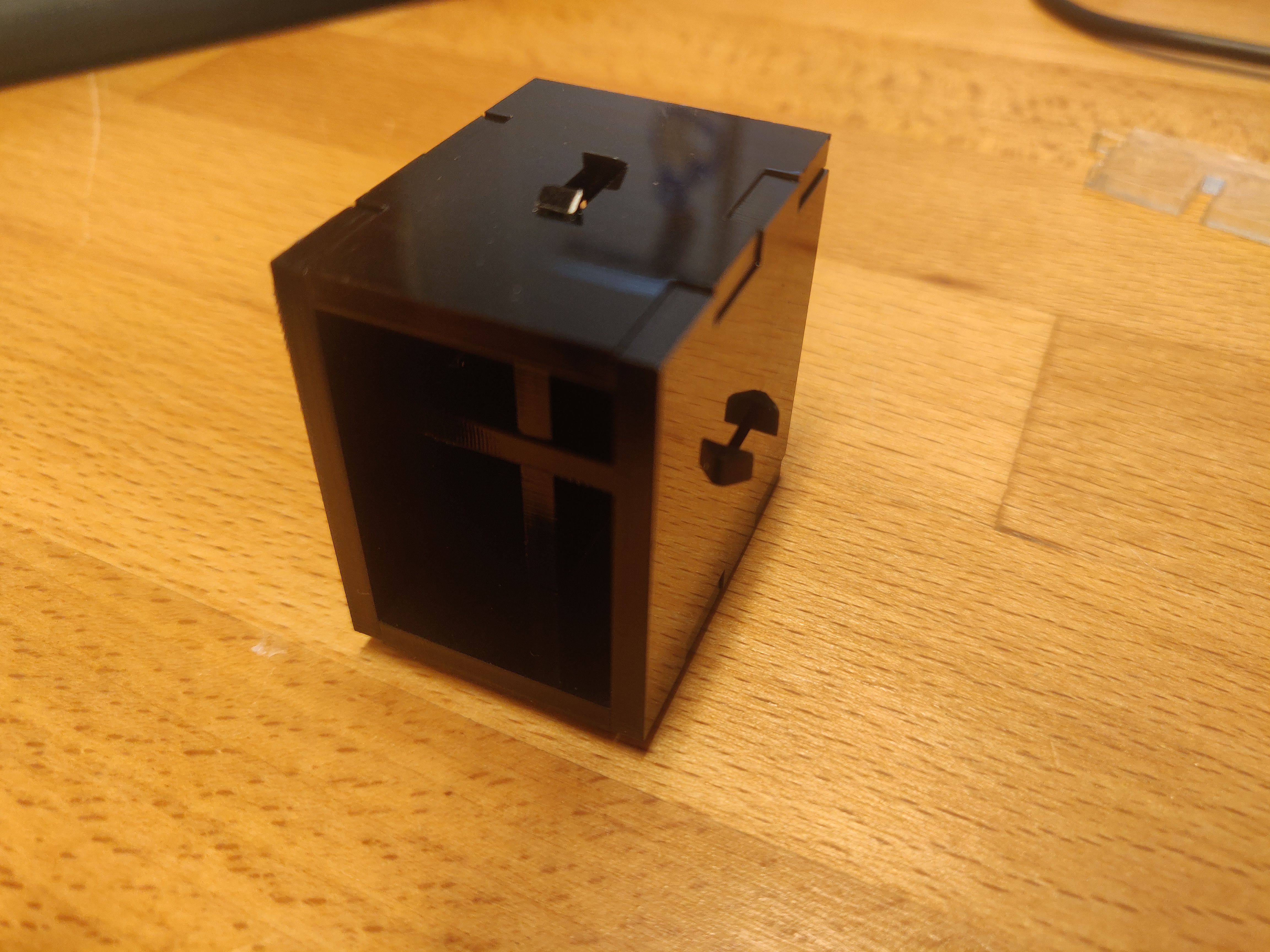
To test the fit I created a short piece of the tube seen here.
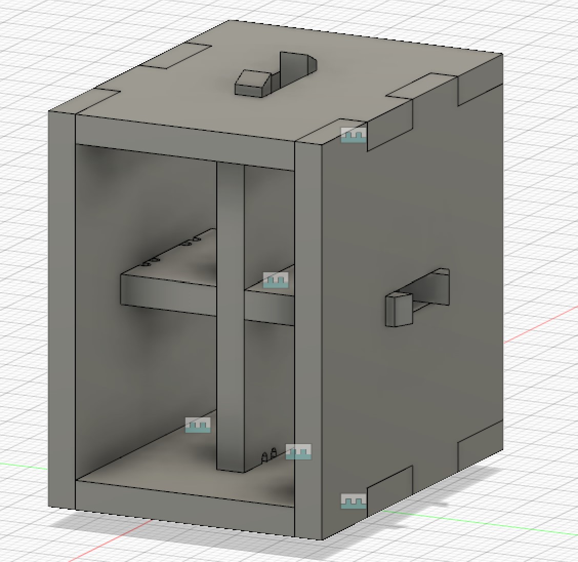
This tube uses 3 types of joints, finger joints for the corners, a press fit to connect the 2 braces and snap fits to connect the braces to the 4 sides
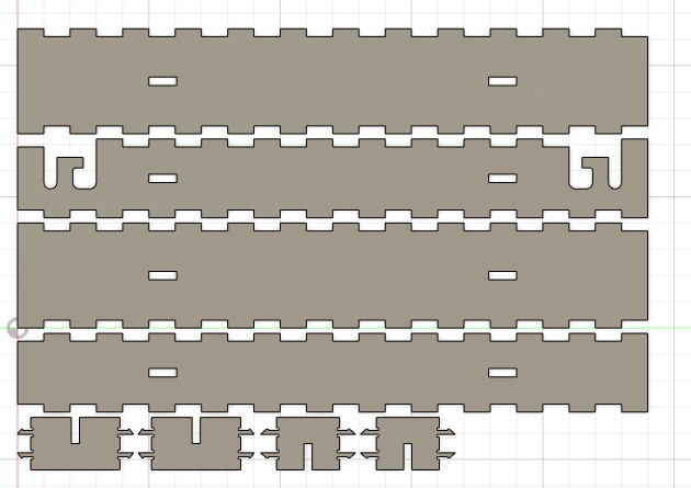
Below you can see the drawing for the top piece as well as the vertical column. These are both drawn only using named parameters and derivatives there of using rectangular paterns for thi finger joints and mirror symmetry wherever possible. The sides and horizontal column are the exact same expept they switch lenght and width.
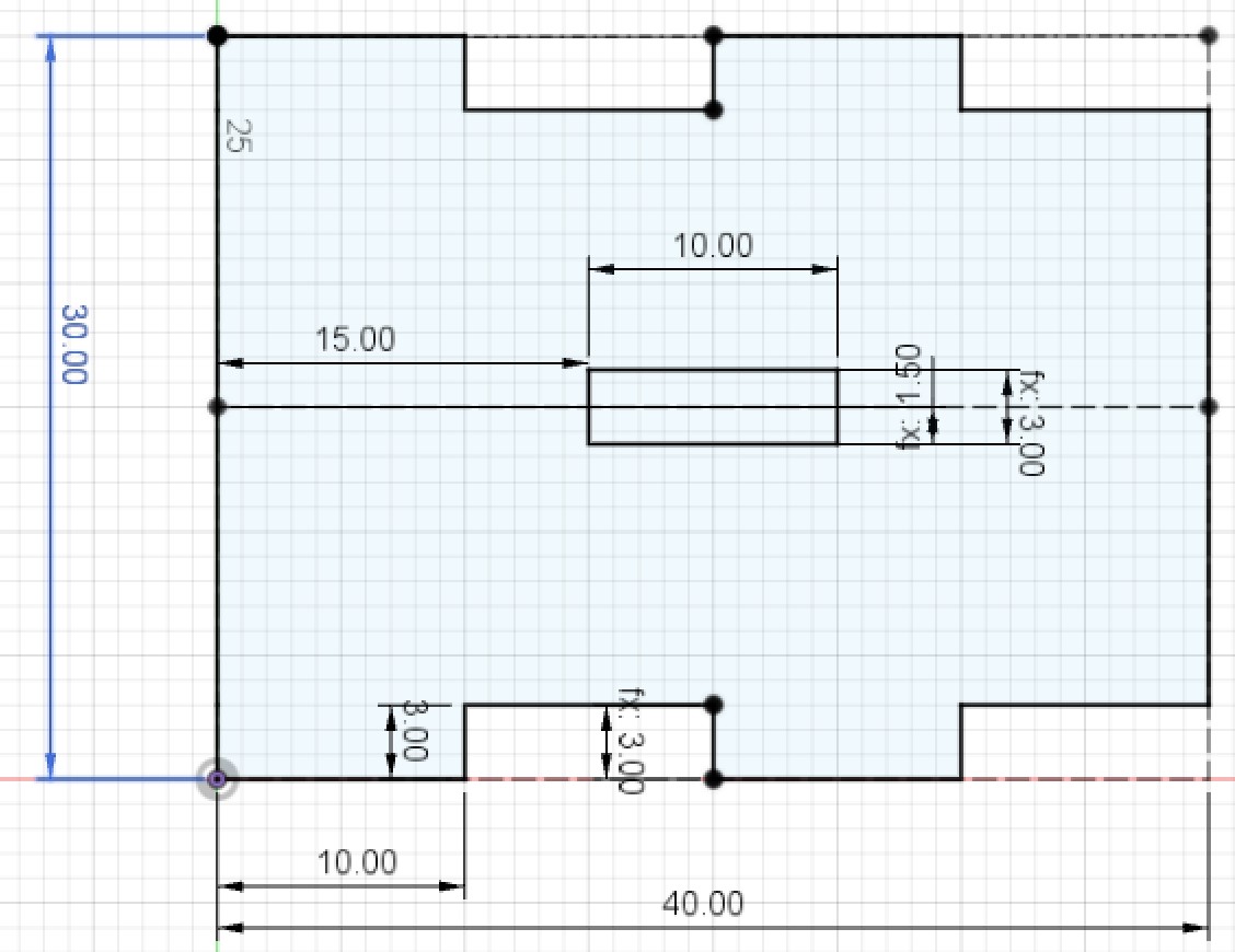
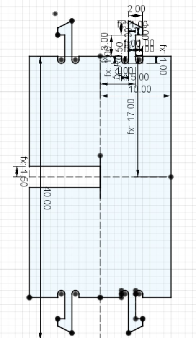
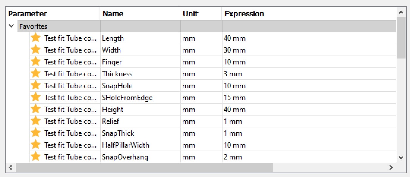
Below you can see all of the parameters that I used.
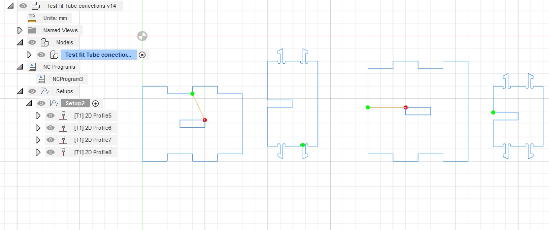
To account for kerf I followed this video to learn how to account for kerf which gave me the following path that I exported as a pdf using the AutoCAD DXF Post library for Fusion found by searching dxf here .
Now that I had the dxf file it was time to import it into inkscape, make copies of the top and side pieces, position them relative to each other. Then I selected all of the pieces, selected Object -> Fill and stroke and input the following settings, fill = none, stroke paint = flat color and stroke style thickness = 0.02 mm. I then saved the file to an usb drive to move it to the laser cutter.
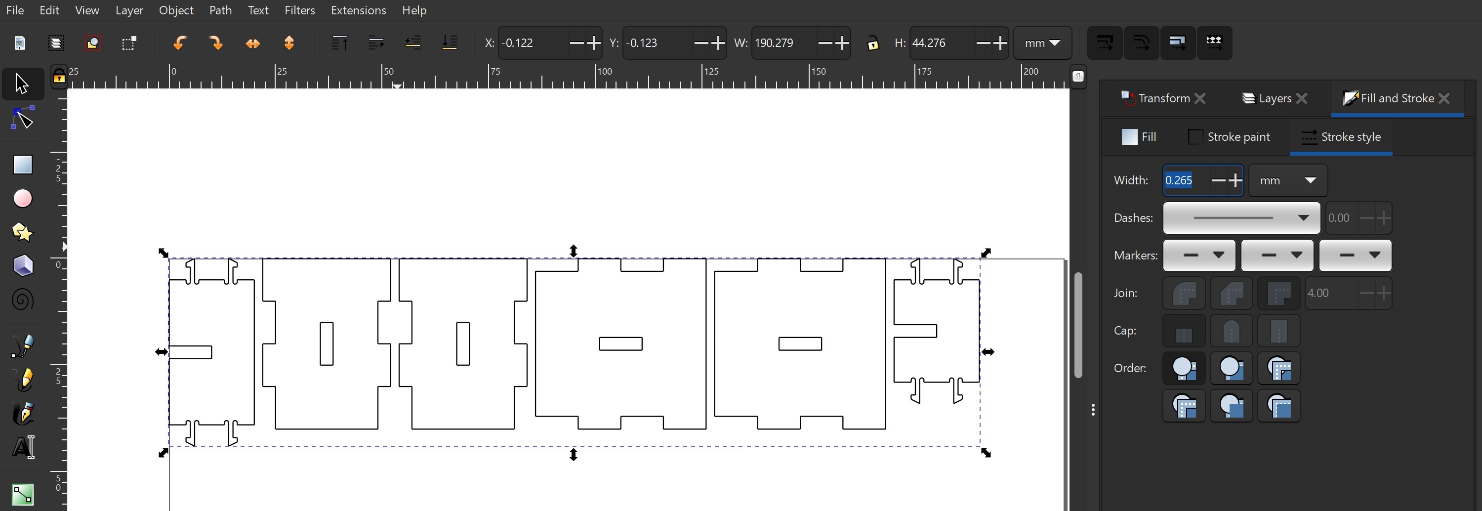
After testing I noticed that a few things were wrong, I had accidentally set the kerf to 0.0133 mm and not 0.133 mm, the snap fits were to thin at 1 mm then to thick at 2 mm but 1.5 mm finally worked. The holes that the snap fit fingers fit into were originally the exact size of the fingers which was too tight, adding 0.6 mm to the lenght and 0.2 mm to the width fixed that. Finally the pressfits between the two columns was to loose at thickness + kerf and to tight at thickness + 0.06 mm so I settled on thickness + 0.1 mm
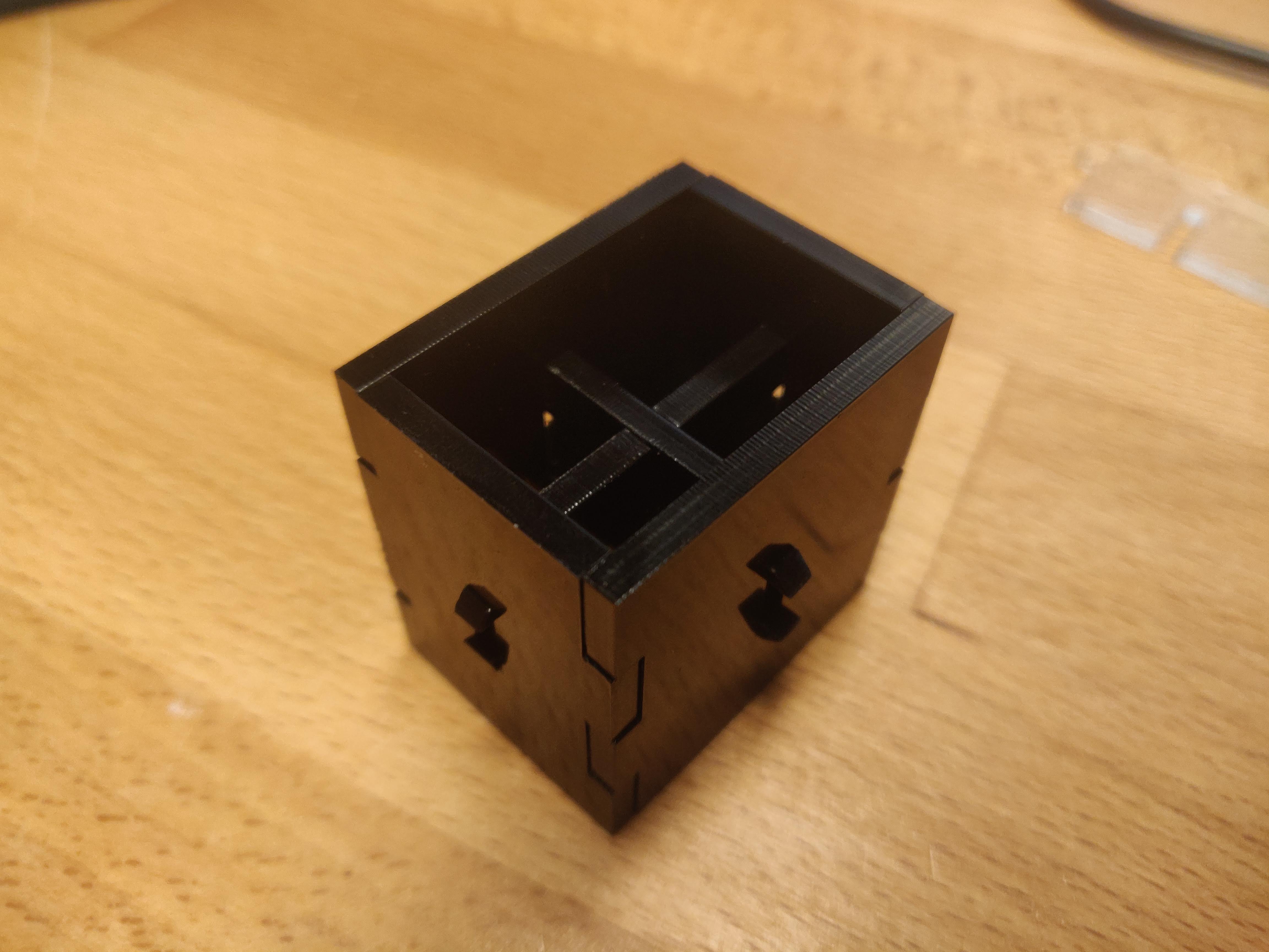
I had done test withboth black and clear acrylic and the resaults weren't consistant so I decided to cut the materials, turns out that the black one that I will be using for the final product is 3.15 mm thick not 3 mm like it was supposed to be, that explains many of my problems but thankfully everything works now and here is the final succesfull test fit. I definetly should have measure everything earlier in the process, saving me many hours of testing.
Worktime 12 hours
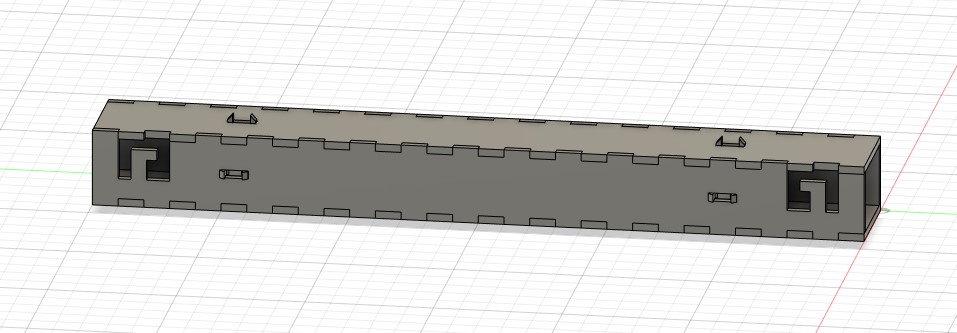
Final design
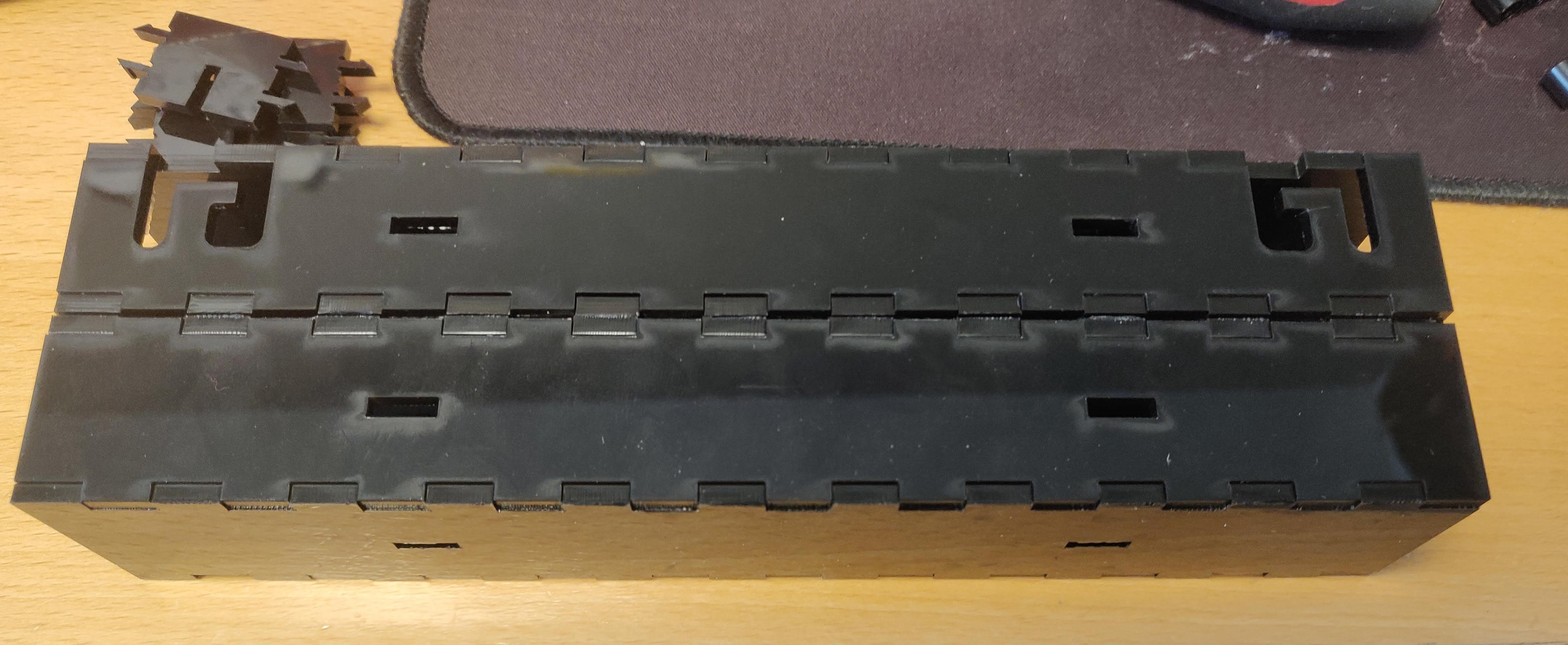
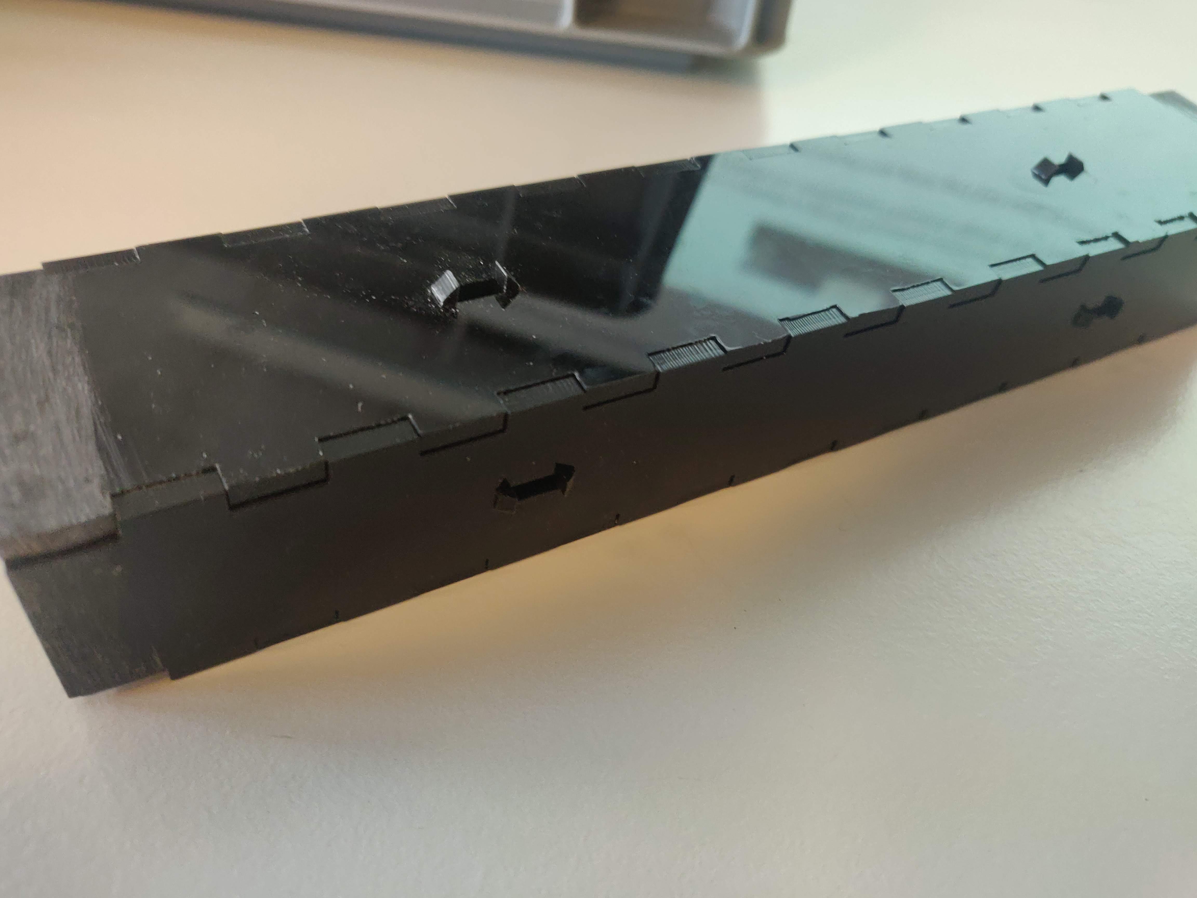
The final design was much the same as the test but with a few changes. The length was changed to 220 mm, another set of columns was added and hooks were added to the top side so that rubber bands could assit the motors in the joints if needed. Thanks to heavy use of parameters the length of all 4 sides could be changed to any multiple of 20 by changing just one number.
Finally this is how one of the 2 finished pieces came out, pre cleaning though. You can see that the ends are sanded down, that is because the material was 3.15 mm thick and not 3 mm but I forgot to change it in fusion and so to get the arms to fit into the 3D printed inserts I needed to sandthe first 10 mm from the ends down about 0.15mm, thankfully I had a dremel to make it easier.
Worktime 4 hours
Finally here you can see a video of us testing both the elbow and wrist of the robot
Here is the file for the arm
Total worktime 19 hours
Work on website 5 hours